|
Schmidt Consulting |
|
Retro Vacuum Tube Proximity Detector |
|
|
|
|
|
Tom Schmidt |
|
4/2/2015 |
|
I recently ran across scanned images of old electronics magazines. That reminded me of one of my first electronics projects, a proximity detector I built for an 8th grade science fair. Thought it would be fun to rebuild it and see what it is like 50 some odd years later. |
What is a proximity
detector?
Proximity detectors work by sensing the effect an object or person has on the environment without the need for direct physical contact. In any building with AC power there is a pervasive alternating electromagnetic field created by current flowing in the power conductors, 60 Hz in the US 50 Hz in the rest of the world. This detector senses an increase in voltage as a person comes near the sensing element to trip a relay.
Original Popular
Electronics Article
The folks at American Radio History have scanned a huge number of old electronics magazines and made them available on the Internet. I stumbled upon the site and was curious if I could find the original Popular Electronics article I used to build a proximity detector back in 8th grade. Sure enough they had the April 1956 magazine. Reading over the article motivated me to think about building it again. It has nostalgia value as it was one of the first electronics projects I had ever built.
The design is based around a 2D21 thyratron, think silicon controlled rectifier (SCR) with a pilot light. The tube is gas filled; once it conducts the gas ionizes maintaining current flow until plate voltage is reduced to quench the arc. The relay is feed directly from the mains. Once the tube conducts the relay pulls in until the negative half cycle, when conduction stops. A capacitor across the relay coil keeps it from chattering during the negative half cycles when there is no current flow through the tube.
Line voltage is half-wave rectified, filtered and regulated by a 0B2 voltage regulator tube. This provides a stable negative 108V reference to the voltage divider used to set thyratron control grid bias voltage. The higher the negative grid voltage the larger the induced AC must be to cause the thyratron to conduct.
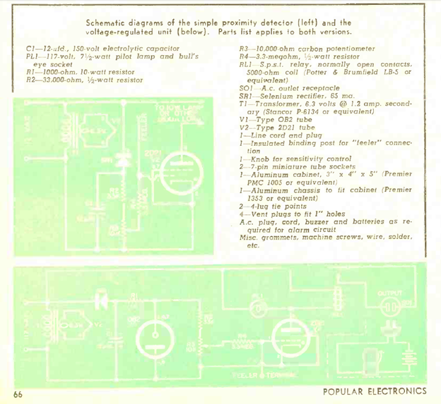
Figure 1 April 1956 Popular Electronic Article
21st Century
Version
In looking over the schematic was somewhat surprised to see there was no isolation. This was before the days of three wire grounded receptacles. Circuit depends on the induced sense voltage being referenced to mains neutral. Hard to imagine an 8th grader building this kind of mains powered electronic project today.
Figured I’d make a few minor changes to increase safety without sacrificing the original design intent and see if it worked as I remember. For authenticity (well actually because my CAD program does not have vacuum tube symbols) dug out my old Pickett plastic templates to draw the schematic.

Figure 2 Front Panel
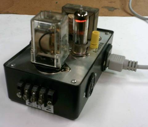
Figure 3 Side View
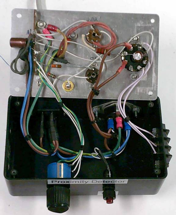
Figure 4 Internal Wiring
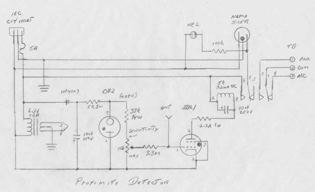
Figure 5 Schematic
Circuitry Changes
I used a modern IEC C-14 fused inlet. This allows the line cord to be removed when the device is not in use and bonds metal chassis parts to safety ground (green wire).
Selenium rectifiers are no longer readily available and are pretty nasty devices to boot, so I substituted a 1N4007 high voltage silicon diode and adjusted the series resistor to limit current flow through the 0B2 voltage regulator. Even assuming a much higher voltage drop of the selenium rectifier regulator tube current in the original design seems excessively high to me. With a 5K resistor and silicon diode current is about 12ma. I used a 3W resistor I had laying around.
The original design called out 12uF 150v cap. The DC voltage out of the half wave rectifier is 170v so that was pretty marginal. Found some 10 uF 250V caps on eBay so used them.
Substituted an enclosed relay, Magnecraft W88CPX-17 5k ohm 7.2ma DC, for the open frame one used in the original design. I added a 2.2k series resistor, not on the original design, to limit 2D21 plate current. The relay has DPDT contacts so used one set to switch AC power to a NEMA 5-15 receptacle and the other connects to a three lug terminal strip. A 10 uF cap across the coil keeps the relay from chattering. The original article used an incandescent pilot light across the relay coil to prevent chattering, I have no idea how that was supposed to work and did not bother experimenting with it.
Located a neon pilot light on the front panel to indicate when output is active.
The original sensitivity adjustment was a 10k pot; I used a 10-turn 10k because that is what I had in my junk box. For safety grounded the shaft.
Smoke Test
Happily when I fired it up it worked as advertised. The 2D21 does not glow when it pulls in the relay; I thought I remembered a purple glow. Perhaps that is dependent on tube construction. This circuit works by capacitive coupling between the object and sense element, so the better the coupling the greater the range. With just wire in the antenna terminal able to sense the palm of my hand about an inch away and just my finger about a ¼ of an inch. With a chunk of circuit board trip range is about 5 inches. Trigger level is a little sensitive as it uses capacity coupled AC to trip the relay so turning on nearby florescent lights affects the trigger level.
According to my handy dandy Kill-a-Watt unit draws 8 watts idle and an additional watt when tripped.
It was fun bringing this back to life, I don’t remember what happened to the one I built back in 8th grade. Now that I’ve built it have no idea what I’m going to do with it. I doubt the new generation of kids, used to the Internet and smart phones will be agog over a two tube proximity detector, but it brought back fond memories for me.