|
Schmidt Consulting |
|
Simple Web Based Aquarium Controller |
|
|
|
|
|
Tom Schmidt |
|
1/9/2015 |
|
We have several fresh water aquariums. Wanted to clean up the mass of cords and timers so used the same Web based PLC I’ve used before to perform lighting and heating control for two tanks. |
Contents
Overview
We have several fresh water aquariums. The largest tank is 100 gallons along with several smaller tanks. I’ve had great success using CAI Networks WebControl PLC for other projects so thought the fish tanks would be a great additional project. Designed the controller so it is able to provide light and heat control for two independent tanks. In addition I incorporated GFCI protection to protect against electric shock.
In addition to my usual design practice of email notifications incorporated a visual and audible alert in the event of GFCI or temperature failure.
If the chassis looks familiar that is because it is recycled TiVo Series II. I’ve used TiVo chassis for several other projects. They are a good size and are well shielded. Removing the front plastic bezel exposes a solid metal panel, part of the lower chassis. Added rubber feet to what was normally the front panel so the controller may be laid flat or stood up on end.
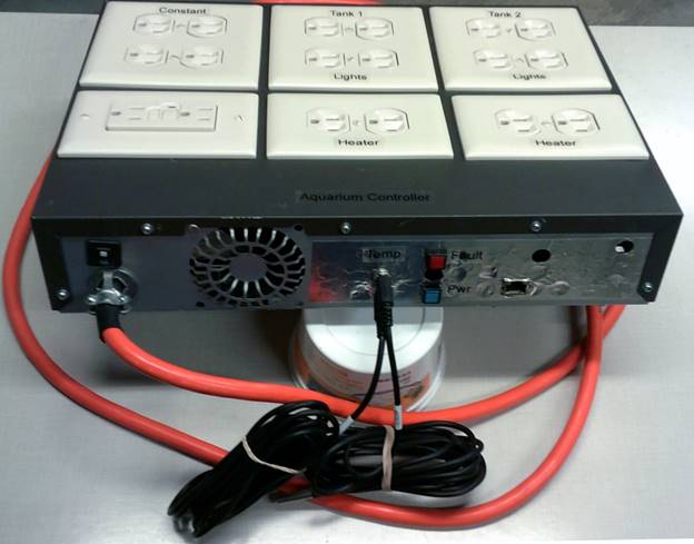
Figure 1 Aquarium Controller
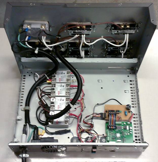
Figure 2 Controller Internals
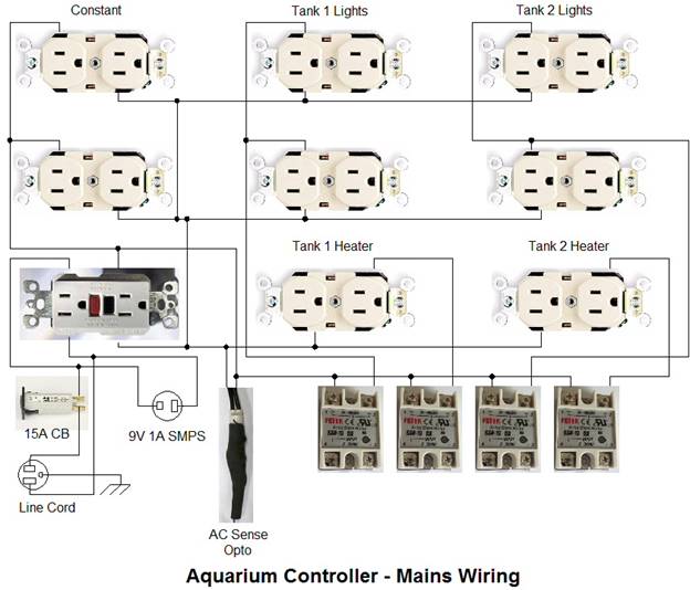
AC Power Distribution
Power is supplied by 12 AWG power cord protected by a 15 circuit breaker. From there power is feed to the line side of a GFCI and to a 9V SMPS that powers the electronics. This way if the GFCI trips the controller remains on so it is able to send an alert email and provide audible/visual fault indication.
The output of the GFCI feeds additional always on receptacles for things like filter pumps. The GFCI protected feed then goes to four SSRs controlled by the PLC. GFCI status is monitored by a neon opto isolator. This provides input to the PLC that the GFCI has tripped.
GFCI Power Line Optoisolator
To allow the controller to monitor the state of the GFCI I built my own opto isolator consisting of a 120V neon pilot light assembly and a GL5516 Cds photo resistor. When exposed to light the Cds resistance drops to a low value. The off state is greater than 500k ohms and when illuminated by the neon light drops to about 1k.
I used heat shrink to attach the Cds cell to the front of the pilot light and prevent entry of extraneous light.
|
|
|
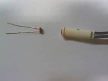
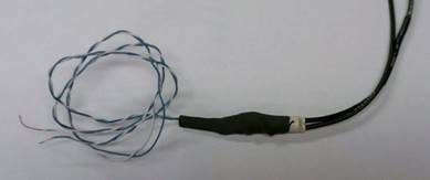
Figure 3 AC Optoisolator
Temperature Monitoring
The WebControl PLC supports Maxim/Dallas 1-wire 18B20 temperature sensors. The two tank sensors connect via 3-wire “stereo” 1/8” phone jacks. A third sensor is mounted on the WebControl board to report chassis temperature. I purchased 3 meter 18B20 waterproof cable assemblies on eBay so all I needed to do was attach the phone plug and label the sensor for tank 1 or 2.
1-wire sensors are individually serialized at manufacture allowing the system to identify individual sensors. I labeled each sensor with a tag indicating Tank 1 or 2. At power up the PLC identifies devices attached to the 1-wire bus and displays the serial number of each sensor. The Temperature Setup page is used to map each sensor to a specific identifier and select how readings are reported, Fahrenheit or Celsius. To determine which serial number relates to which sensor unplugged the two tank sensors, the remaining one was the built in temp sensor, then reconnected the tank sensors one at a time to add them to the controller.
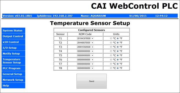
Figure 4 Temperature Sensor Configuration
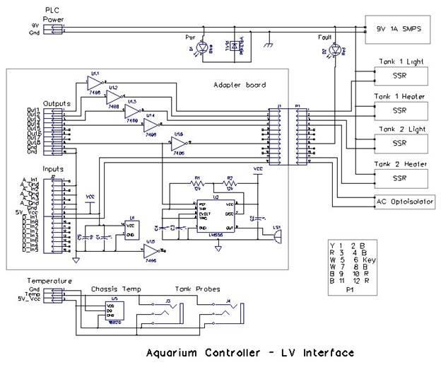
Adapter Board
A small perf board is used to interface the WebControl to the system. A 7406 open collector buffer drives the SSR control input and the red fail light. A LM555 is used as a crude tone generator to drive a small speaker producing an annoying audible alert. The red fail indicator and audible alarm are driven by one of the PLC outputs. Firmware pulses the light/speaker in a 1sec on, 3 sec off pattern.
WebControl Pages
The WebControl user interface is pretty basic. One of the many projects on my to-do list is to create a more user friendly interface to the multiple controllers around the house. However in the meantime we are using the PLC barefoot.
Network Access
The Ethernet port is only 10 Mbps but as there is not much data flowing between the LAN and PLC that is not a serious limitation. The network interface may be configured as either DHCP or static. I typically set these controllers statically so their address is constant even if I change the LAN router. As mentioned set the NTP address to a local LAN based time server. Web pages can be configured to require log in credentials if desired and limited to specific IP addresses.
After a reset the static IP address is 192.168.1.15 and ID/Password set to admin/password. I normally connect my laptop directly to the controller to change the IP configuration and once configured connect it to the LAN. If needed there are a pair of reset terminals on the board to default the system back to factory defaults.
Operating Parameters
The four UROM values allow changing setting without messing with the firmware. There are two user settings for each tank, light on time and temperature. UROM1 and 2 are for tank 1 URMO3 and 4 for tank 2.
UROM 1 and 3 are set to an integer value between 0-15 to specify how long the light is on. If the value is greater than 0 the controller turns the light on at 6AM and off the specified number of hours later. I did not bother to set Daylight Savings Time on the controller, seemed like an unnecessary complexity.
The PLC supports Internet network time protocol (NTP) to automatically set time and date. Normally these values are obtained from an Internet server pool, such as: us.pool.ntp.org organized by the NTP Pool Project. In my case I’m running my own time server on the LAN using a program called: Tardis so instead of pointing the PLC to the Internet it obtains time from a local server. The advantage of this arrangement is even if we lose Internet connectivity time will still be set on the PLC.
The temperature setting monitors the respective 1-wire sensor to control the thank heaters. Internally the PLC computes temperate in .1 degree increments. To make setting the control point more convenient settings are done in one degree increments. User code simply multiples UROM value to 10. The control function includes 2 degrees of hysteresis. The PLC turns on the heaters if temperature falls below the set point by 1 degree and off when it exceeds set point by 1 degree. The mechanical thermostats on each tank heater are set a few degrees higher as a fail-safe.
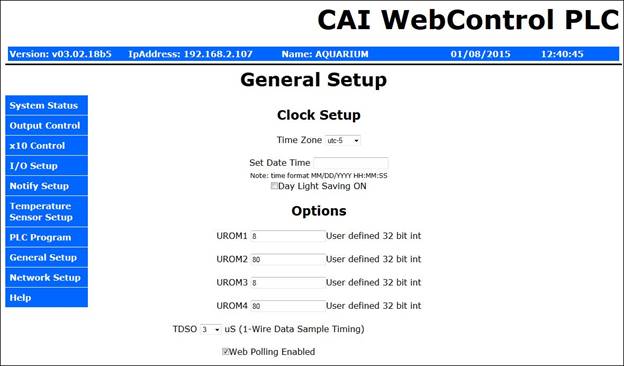
Figure 5 Temperature and Lighting Settings
Email Notification
The PLC controller support up to 8 email messages. Beside the subject and message text the email includes most of the registers and temperature sensor data. Two emails are dedicated to UROM parameter checking. Firmware detects UROM value change and does a bounds check to see if new value is acceptable and sends the appropriate in range or out of range email with a list of valid parameters.
A third email is used for diagnostic purposes, it is sent at power up and if the GFCI trips or one of the temp sensors is reported as bad.
One item to note is this version of the WebControl supports email account authentication but not SSL/TLS encryption. This may be an issue as more and more ISPs and 3rd party email providers require SSL/TLS. Luckily my ISP does not.
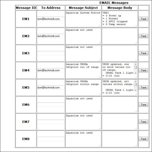
Figure 6 Email Setup
I/O Setup Page
Some of the I/O can be configured to support multiple functions. In our case we are and not using any of the special function so configured Input 1 as a general purpose input. Also note Global PLC radio button is enabled. This allows PLC firmware to control I/O.
The Default output configuration enables both direct web browser and PLC access. To protect specific outputs from being manually changed by the browser uncheck the specific box. The way the aquarium controller code is written even if an output bit it changed by the browser it will quickly be reset the correct state. Leaving browser control enabled can be handy for debug to force an output change and monitor what happens.
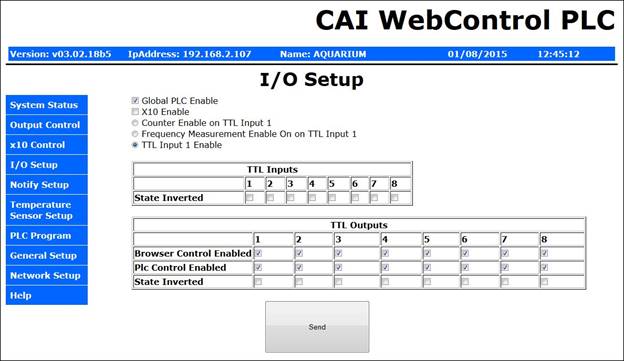
Figure 7 I/O Setup
Status Page
The default PLC page is the stats page. This displays current value of input/output bits, VAR registers and temperature. I did not install a humidity sensor so humidity is always reported as 0%.
Temperature 1, is tank 1, 2 is tank 2 and 3 is chassis
Output 1 is tank 1 light, 2 tank 1 heater, 3 tank 2 light, 4 tank 2 heater and 8 the fail alarm
Input 1 is GFCI status
VAR 1 is used as a system state register: 0, power up, 1 normal operation, 2 GFCI trip, 3 bad temp sensors
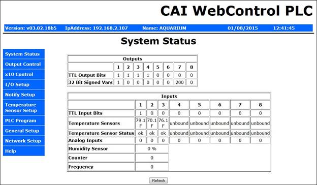
Figure 8 Status Page
Appendix A – Schematic
Appendix B – PLC Code
Aquarium Controller
T. Schmidt
*********** Change Log *********************
12/28/2014 Install
12/21/2014 Code start
11/23/2014 Project start
*************** PCB Hardware/Firmware version ****************
Hardware: 2.2.2
Firmware: 3.2.18b5
Customer loop executed every ~50ms
VAR and RAM initialized to 0 by system
To reset PLC - update Network settings
WebControl takes about 400ms to init I/O at power up
Per CAI Support Temp sensors take up to 2 sec to stabilize at power up
Email takes about 1.5 sec to send.
TTL inputs have 10k to ground pulldown
Output buffer current 10mA per output, 30mA total
9V Power consumption
175ma PLC only (Live Ethernet serving web page)
xxxma Through PLC, PLC & interface board
xxxma Total 9V, PLC, i/f bd, 4-SSR on, audio alarm constant
***************** I/O Defs **********************
Analog Inputs
-------------
AIP1 - not used
AIP2 - not used
AIP3 - not used
Digital Inputs
--------------
IP1 - AC Opto voltage sensor
IP2 -
IP3 -
IP4 -
IP5 -
IP6 -
IP7 -
IP8 -
Digital Outputs
---------------
OP1 - Tank 1 lights
OP2 - Tank 1 heater
OP3 - Tank 2 lights
OP4 - Tank 2 heater
OP5 -
OP6 -
OP7 -
OP8 - Audible/visual alarm
Temperature Sensors
-------------------
T1 - Tank 1
T2 - Tank 2
T3 - Chassis air
T4 - Not used
T5 - Not used
T6 - Not used
T7 - Not used
T8 - Not used
Temp Sensor status (1 = OK)
------------------
TS1
TS2
TS3
TS4
TS5
TS6
TS7
TS8
Humidity Sensor
---------------
H1 - Not installed
Email message Identifiers
-------------------------
EM1 - System Fail (Fail code in VAR1)
EM2 -
EM3 -
EM4 - UROM value out of bounds
EM5 - UROM value within bounds
EM6 -
EM7 -
EM8 -
Variables
--------
VAR1 - Status mode 0=powerup, 1=normal, 2=GFCI trip, 3=Temp sensor fail
VAR2 -
VAR3 -
VAR4 -
VAR5 -
VAR6 -
VAR7 - Bad sys email GFCI/temp: 0=send email, 1-200 debounce, 201 email sent
VAR8 -
RAM
---
RAM1 - Scratch
RAM2 -
RAM3 -
RAM4 -
RAM5 -
RAM6 -
RAM7 - Sum of current UROM values
RAM8 -
Web constants
------------
UROM1 - Tank 1 light timer, 0-15 (0=off) 1hr increments
UROM2 - Tank 1 temp 0-90F (0= off) 1F increments
UROM3 - Tank 1 light timer, 0-15 (0=off) 1hr increments
UROM4 - Tank 2 temp 0-90F (0= off) 1F increments
**************************************************
SYSCHK
Power up init, update VAR1 if GFCI trips or bad temperature sensor status
Monitors 1-wire temp sensor status, debounces bad status. Email sent on
either condition. Fail status automatically corrected if GFCI power back
on or temp status OK
UROMCHG
Sums all 4 UROM values. Sends in bound or out of bound email once per change
event and at power up. If any UROM is out of range all light and heat
outputs set to off.
ALARM
Creates audible and visual alarm. On 1sec, off 3sec
TxLIGHT
Tank lighting. Off before 6AM. On for duration set by UROM1, tank 1
or UROM3 tank 2. If UROM set to 0 - light always off. If out of range that
channel is ignored.
TxHEAT Tank heaters. Temp controlled +/- 1F around set point UROM2 tank 1,
UROM4 Tank 2. If sensor fails output forced off. If out of range that
channel is ignored.
******************* Code *************************
START
CALLSUB SYSCHK
CALLSUB UROMCHG
CALLSUB ALARM
CALLSUB T1LIGHT
CALLSUB T2LIGHT
CALLSUB T1HEAT
CALLSUB T2HEAT
END
SYSCHK:
TSTEQ VAR1 0
CALLSUB STRTDLY
TSTEQ IP1 0
GOTO BADPWR
TSTEQ VAR1 2
CALLSUB GOODPWR
AND TS1 TS2 RAM1
AND TS3 RAM1
BZ BADSENSOR
SET VAR1 1
SET VAR7 200
RET
STRTDLY:
EMAIL EM1
DELAY 10000
SET VAR1 1
SET VAR7 200
ADD UROM1 UROM2 RAM7
ADD UROM3 RAM7 RAM7
ADD UROM4 RAM7 RAM7
CALLSUB RANGECHK
BZ RANGEOK
EMAIL EM4
SET OP1 0
SET OP2 0
SET OP3 0
SET OP4 0
RET
RANGEOK:
EMAIL EM5
RET
RANGECHK:
TSTLT UROM1 0
RET
TSTGT UROM1 15
RET
TSTLT UROM2 0
RET
TSTGT UROM2 90
RET
TSTLT UROM3 0
RET
TSTGT UROM3 15
RET
TSTLT UROM4 0
RET
TSTGT UROM4 90
RET
RET
BADPWR:
SET VAR1 2
TSTEQ VAR7 201
RET
SET VAR7 201
EMAIL EM1
RET
GOODPWR:
SET VAR1 1
SET VAR7 200
RET
BADSENSOR:
SET VAR1 3
TSTEQ VAR7 201
RET
DEC VAR7
TSTNE VAR7 0
RET
EMAIL EM1
SET VAR7 201
RET
UROMCHG:
ADD UROM1 UROM2 RAM1
ADD UROM3 RAM1 RAM1
ADD UROM4 RAM1 RAM1
TSTEQ RAM7 RAM1
RET
SET RAM7 RAM1
CALLSUB RANGECHK
BZ UROMOK
EMAIL EM4
RET
UROMOK:
EMAIL EM5
RET
ALARM:
TSTGT VAR1 1
GOTO ALARMON
SET OP8 0
RET
ALARMON:
ANDB CS 0x03 RAM1
TSTEQ RAM1 0 OP8
RET
RET
T1LIGHT:
TSTLT UROM1 0
RET
TSTGT UROM1 15
RET
TSTLT CH 6
SET OP1 0
ADD 6 UROM1 RAM1
TSTLT CH RAM1 OP1
RET
RET
T2LIGHT:
TSTLT UROM3 0
RET
TSTGT UROM3 15
RET
TSTLT CH 6
SET OP3 0
ADD 6 UROM3 RAM1
TSTLT CH RAM1 OP3
RET
RET
T1HEAT:
TSTLT UROM2 0
RET
TSTGT UROM2 90
RET
TSTEQ TS1 0
GOTO BADT1SENS
SUB UROM2 1 RAM1
MUL RAM1 10 RAM1
TSTLE T1 RAM1
SET OP2 1
ADD UROM2 1 RAM1
MUL RAM1 10 RAM1
TSTGE T1 RAM1
BADT1SENS:
SET OP2 0
RET
T2HEAT:
TSTLT UROM4 0
RET
TSTGT UROM4 90
RET
TSTEQ TS2 0
GOTO BADT2SENS
SUB UROM4 1 RAM1
MUL RAM1 10 RAM1
TSTLE T2 RAM1
SET OP4 1
ADD UROM4 1 RAM1
MUL RAM1 10 RAM1
TSTGE T2 RAM1
BADT2SENS:
SET OP4 0
RET
******************* End **************************