1 ISP Overview
Internet popularity is driving demand for ever-faster service, and exerting downward pressure on price. Connection between end user and ISP is often called the last-mile. This implies there is a magical entity out there called “The internet” and customers are passive consumers of internet goodness. I prefer the term first-mile. It better denotes internet value being the result each person’s connection as both contributor and consumer. Today most citizens in industrialized countries have access to some form of high-speed access. Broadband is increasing seen as a utility without which citizens are unable to fully participate in modern society.
Broadband is a much abused and inexact term. The United States Federal Communication Commission is constantly redefining the definition of minimum broadband speed. In 2015 it was set to 25 Mbps download and 3 Mbps upload. In 2024 the definition was increased 100 Mbps download and 20 Mbps upload.
Most of us utilize an internet Service Provider (ISP) to access the internet. The ISP owns leases or otherwise has access to a connection to each customer. The picture below provides a high level overview of how ISPs connect customers to the internet.
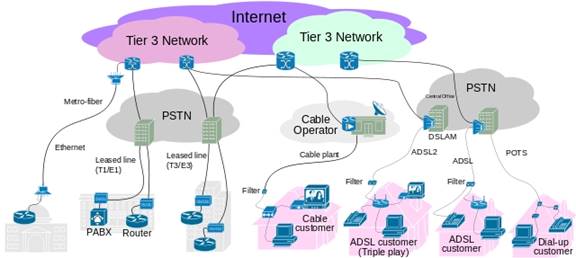
Figure 1 ISP Functional Block Diagram
Connecting to an ISP would not have much value if the only people you can communicate with are other ISP customers. To provide worldwide connectivity ISPs connect to other ISPs at peering points. This allows traffic to be delivered anywhere in the world.
ISPs exert a great deal of control over how customers use the internet. Much is made of internet robustness and redundancy. That is true of the internet in general but for most of us the ISP acts as the on-ramp gatekeeper, limiting how it can be used. In most locations broadband competition is nonexistent or extremely limited. ISP business policy has significant impact on how customers use the internet and how new internet services are deployed.
There are several essential functions that must be provided by the ISP, as they are the only entity capable of doing so. There are many services, often associated with ISPs, which can be provided by anyone. The distinction between essential and non-essential functions is important when discussing Network Neutrality. As broadband access becomes more pervasive ISPs and policy makers need to balance business considerations with public interest.
Essential Core Functions
· Customer Connection
· Customer Authentication
· Customer Address Allocation
· Packet Routing
· Peering
· Multicast (IGMP)
· Quality of Service (QoS)
· Service Level Agreement (SLA)
· Acceptable Use Policy (AUP)
· CAELA
· Customer Support
· Billing
Non-Essential Services
· Name Resolution (DNS)
· Usenet
· Web Hosting
· Cloud Based File Storage
· Virtual Private Network
· Voice over IP
· Fixed Mobile Convergence
· IP Radio
· IP Television
1.1 Essential Core Functions
ISPs deliver a suite of services. When evaluating an ISP it is important to keep in mind which features are core functions, only the ISP can provide, and which are value add that can be provided by a third-party.
1.1.1 Customer Connection - Physical
First and foremost the ISP needs to provide a method for customers to access the ISP network.
Some ISPs own the First-Mile access network; Cable and fiber to the premise (FTTP) are examples of this type of ISP. The ISP owns and manages the outside plant customer connection. DSL ISPs typically rent physical access to legacy copper phone line from Incumbent Local Exchange Carrier (ILEC) and collocate their equipment in the phone company central office.
Dialup ISPs use the PSTN (Public Switched Telephone Network) to connect customers. The ISP creates regional points of presence (POP) near the customer so customer is able to call a local ISP telephone number, avoiding per minute charges. The ISP in turn digitally terminates phone lines to support V.90/92 dialup speeds.
Wireless ISPs both fixed and cellular do not provide a physical connection at all. Rather they obtain a government license to use the public airwaves to connect customers. This applies to both fixed and mobile wireless. The customer connects to the ISP’s radio network and traffic is then transported much the same as other ISPs.
Customer interface requirements differ greatly depending on type of service and whether or not the ISP provides the network access device. For example Cable and DSL ISPs typically provide the customer with a standard’s based modem router with an Ethernet or WiFi interface. Fiber optic service requires an ONT (optical network terminal) that converts the optical signals into copper Ethernet and optionally to legacy land line telephone and Cable TV. In the US T-1 carrier is a tariffed telecommunication service. The FCC defined customer interface as two pair copper circuit typically implemented via a smart-jack. Dialup ISPs require customer obtain a V.90/92 or ISDN modem. Fixed wireless ISPs typically supply and install customer antenna and radio. Cellular providers often provide a subsidized smart mobile phone when a customer signs up for service. However this trend is in decline with customers often able to purchase an unlocked phone on the open market.
1.1.2 Customer Connection – Logical
ISP provides either a routed or bridged customer connection. Residential accounts are typically bridged; customer connects to ISP as if they were part of the ISP LAN. VLAN techniques prevent users from seeing each other’s traffic. Business class accounts are typically routed rather than bridged. ISP’s edge router communicates with customer’s edge router. Routed connections are more flexible, but also more complex, then bridged.
1.1.3 Authentication
The ISP needs a mechanism to insure only authorized customers connect to its network. For some types of service the link between customer and ISP is hardwired so any traffic appearing on the link is assumed to originate from customer. T1 and FTTP are typical hardwired connections. Shared media such as Cable and wireless need a way to identify customer. DOCSIS modems include a digital signature to prevent unauthorized access. ADSL ISPs typically use PPPoE (Point-to-Point Protocol over Ethernet) to authenticate customers. Telco’s like PPPoE because it facilitates support for third-party ISPs. Dial up ISPs typically utilize PPP (Point-to-Point Protocol) to authenticate customers.
1.1.4 Address Allocation
Each internet host requires a unique address. ISPs typically provide residential customers with a single IPv4 address. Large customers may obtain their addresses directly from ICANN (Internet Corporation for Assigned Names and Numbers) or from wholesale ISPs. IPv4 defines a 32-bit address space yielding about 4-billion possible addresses. That was a large number back when the internet was limited to a few educational and government institutions but has become a serious limitation today. As a result IPv4 addresses are in very short supply. Next generation internet protocol IPv6 increases address space to 128-bits, a truly humongous number. With IPv6 even residential customers are issued a large block of addresses. The transition to IPv6 has been glacially slow because it is not backward compatible with IPv4.
If the ISP does not have access to enough public IPv4 addresses they use CGNAT (carrier grade network address translation). Essentially the ISP performs the same operation as residential users use to share a single IP address among multiple customers.
IP addresses serve multiple functions. They denote a specific internet host; each host needs an IP address. IP addresses also facilitate routing because they are allocated in blocks. If IP addresses were issued randomly each router would need to potentially look through billions of addresses to determine how to handle each packet. By aggregating addresses into large blocks routers only need look at a few high order address bits to determine how to forward packets.
Business accounts are typically configured statically. Static allocation is preferred for commercial accounts. With a static address customer settings are configured manually, based on information provided off-line by the ISP. This eliminates possibility of address change interfering with remote access.
Most residential accounts obtain IP address dynamically. This is convenient because it eliminates need for non-technical customers to manually configure IP address, subnet mask, gateway address and DNS server address. Dynamically assigned address may change at any time making it difficult to operate servers.
1.1.5 IPv6 Support
February 2011 witnessed a
major milestone on the journey to mass deployment of IPv6, IANA made the final allocation of IPv4
addresses. This event has been long anticipated but having finally occurred
ought to spur more rapid deployment of IPv6, the successor to IPv4. IPv6
represents a significant improvement over IPv4 but adoption has been painfully
slow. The reason is IPv6 is not backward compatible with IPv4. This is because IPv4
has a 32 bit address space supporting approximately 4 billion hosts (4.3 x 10⁹)
IPv6 uses 128 bits for a mind boggling 340 Undecillion hosts (3.4 x1038).
The massive address space allows large blocks of address to be allocated, thus
easing routing and management.
Since IPv6 is not backward compatible ISPs offer a number of ways to support the transition.
1) Dual-Stack is probably the easiest to understand. The ISP provides customer with both IPv4 and IPv6 addresses. Customer equipment uses the appropriate version to communicate with the remote host, preferentially using IPv6. The down side of this implementation is the need to provide the customer with a public routable IPv4 address and the customer network gear has to support both IPv4 and IPv6. The lack of IPv4 addresses is why it is imperative the internet adopt IPv6.
2) Dual-Stack lite The ISP provides only IPv6 addresses to customers, all traffic between customer and the ISP network is IPv6. When a customer accesses an IPv4 internet host the customer’s router encapsulates the IPv4 address and transports it over the IPv6 connection to the ISP. The ISP uses CGNAT (carrier grade NAT) much like the way a typical home network shares a single IP address today. Customer’s router disencapsulates IPv4 packets and distributes IPv4 and IPv6 packets within the LAN. Just to keep life interesting the term CGN has been depreciated and it is now called large scale NAT (LSN) to more accurately reflect what the technique does.
3) Tunneling (6in4) is a way for IPv6 packets to be transported over an IPv4only network to another IPv6 network. This is probably not of interest for most readers of this paper but is very useful for companies with many locations that have adopted IPv6 internally.
A significant force driving IPv6 adoption is the cellular phone network, especially outside the US where the IPv4 shortage is more acute. The proliferation of smart phones means the network needs to hand out an IP address per person rather than per residence greatly increasing the number of addresses needed.
1.1.6 Packet Routing
The term internet is a contraction of inter network. Internet is literally a network of networks. Routers are used to forward packets between networks. Devices know whether or not a host they are trying to reach is local. To access a remote host packets are forwarded to a router, called a gateway, attached to the local area network LAN. The router uses its knowledge of connection topology to make intelligent forwarding decisions. This process is repeated multiple times until packet finally reaches its ultimate destination. Routers learn connection topology by exchanging routing information. In the case of most residential customers this forwarding decision is trivial as there is only one connection to the internet.
1.1.7 Transit Network
Signing up with an ISP would not be very useful if customer was limited to only communicating with other customers of the same ISP. The early internet consisted of a few nodes interconnected by point-to-point links rented from the old Bell System. As the internet grew it became apparent there was a need for a high-speed data network to interconnect high usage nodes. Transit providers span continents and oceans providing the backbone. Transit providers exchange traffic with each other and accept traffic from ISPs. Large companies, ISPs and governments often connect directly to one another, called Peering, eliminating the need to use a transit provider for some traffic. Smaller ISPs purchase bandwidth from third party wholesale suppliers. The end result is regardless how one connects it is almost always possible to communicate with anyone else on the internet.
This drawing is very simplified; typically all but the smallest ISP will have multiple connections to various transit providers and often peering connections to other ISPs. Routing protocols chose the best route to deliver each packet. One of the network neutrality concerns is that ISPs will choose less congested routes for partners resulting in slower performance if a customer is accessing a non-preferred site.
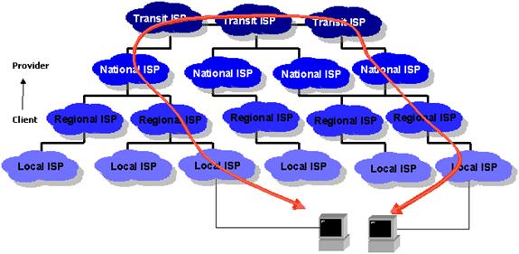
Figure 2 Peering
1.1.8 Multicast (IGMP)
Internet is a powerful communication medium. A user is able to connect to another host anywhere in the world virtually instantly. As powerful as this type of communication is it is not well suited for broadcast, the delivery of one program to many subscribers simultaneously. Traditional broadcast business model grew out of the technical limitation of radio. Station owner built a transmitter and anyone within range was able to receive the broadcast.
The one-to-one connection model used by the internet makes it difficult to cost effectively broadcast programs since each listener requires a unique network session. IGMP (internet group management protocol) creates the infrastructure to deliver a single stream to multiple users. At each branch a decision is made whether or not to forward the stream. If an active listener is downstream packets are forwarded, if not they are dropped. This conserves channel capacity by suppressing streams no one is listening to. IGMP dramatically reduces server load since only a single copy is transmitted. Internet broadcasting is still in its infancy and IGMP is not commonly implemented by ISPs. For multicast to function each router between sender and receiver needs to support IGMP.
1.1.9 QoS (Quality of Service)
The internet is an egalitarian best effort network. This works amazing well for transferring large chunks of data from point A to point B. The network continues to operate in the presence of all sorts of impairments and failures. However: best effort does not work well with latency critical applications such as telephony and streaming media when dealing with network congestion. For example a Voice over IP (VoIP) phone call requires round trip latency under 150ms. Excessive delay makes carrying on a conversation difficult and when extreme virtually impossible. On the other hand if a print job is delayed a little no one is likely to notice as long as it completes successfully.
When a switch or router encounters congestion it buffers incoming packets until it is able to forward them. Normally this occurs on a first in first out (FIFO) basis. Quality of Service (QoS) metric allows latency sensitive packets to receive priority queuing. This simple strategy works well if latency critical traffic is a small percent of total. QoS marks packets with a (Diffserv) priority level. When congestion occurs higher value packets are delivered first. Lower value packets are delayed or discarded during periods of extreme congestion. QoS service allows more graceful degradation by moving high priority packets to the head of the queue.
As discussed in a later section traffic shaping and preferential packet treatment is controversial. Network Neutrality proponents are concerned ISPs will strike business deals with partners to preferential deliver their data at the expense of competitors. It is important to remember Quality of Service mechanisms do not provide additional channel capacity. They simply redefine winners and losers. When channel capacity does not meet “offered load” (an old telecom term) some policy must be in place to deal with congestion. The PSTN managed congestion by withholding dial tone or returning an “all trunks busy” message when calls could not be completed. The internet handles congestion by delaying packets or in extreme cases dropping them. QoS controls which packets get delayed. Many argue deploying additional capacity is more cost effective then implementing a complex differential service mechanism.
To be maximally effective QoS requires end-to-end deployment. Technical and business problems facing QoS is much the same as IGMP. There is little value until “everyone” deploys it and little incentive to be an early adopter. ISP and all intermediate nodes need to monitor packet privilege level and treat them accordingly. Controls at each level need to monitor statistics to prevent “tragedy of the commons.” If too many packets ask for priority handling they all suffer.
Historically most residential broadband service is asymmetric; download is much faster than upload. There is benefit in shaping upload traffic so higher priority traffic is treated preferentially at the edge of the customer’s network. Customer’s edge router examines outbound packets and prioritizes them. Many residential routers already do this to a limited extent giving TCP/IP ACKs preferential treatment. Similar treatment may be applied to VoIP or critical gaming packets.
1.1.10 SLA (Service Level Agreement)
One of the main differences between residential and business accounts is the SLA (Service Level Agreement). SLA defines things like: minimum speed, maximum latency, service reliability and mean time to repair. The SLA imposes performance guarantees ISP must meet and penalties if they do not. This is one of the reasons business class service is so expensive. Residential accounts are typically best effort. If connection fails or experiences congestion ISP is under no obligation to correct problem on an expedited basis.
1.1.11 AUP (Acceptable Use Policy
AUP (Acceptable use policy) defines customer responsibility, how service may be used and penalty for misuse. For example, residential customers are typically prohibited from reselling access or running servers and ISP’s often block certain types of traffic. In an attempt to reduce cost some residential ISPs impose usage caps to limit monthly download and upload. Most ISP’s reserve the right to revise the AUP at any time making for a pretty one-sided contract.
1.1.12 CALEA (Communication Assistance for Law Enforcement Act)
CALEA passed in 1994 and has been greatly expanded over the years. It requires the ISP to install special equipment to facilitate wiretapping of customer’s digital traffic by law enforcement. Originally it was limited to voice traffic but has been expanded to include all ISPs. There is a lot of pressure on ISPs to retain customer web browsing history and to make it available to law enforcement and antiterrorism agencies. This has been especially prevalent in Europe but is also happening in the US.
1.1.13 Technical Support
Regardless of how good service is on occasion will be necessary to contact technical support to resolve problems. Tech support responsiveness dramatically affects overall customer satisfaction.
Most residential broadband providers offer only limited help in troubleshooting problems. Finger pointing can be frustrating when a customer is trying to resolve a complex interaction and ISP does not consider it their responsibility. Specialized web sites such as DSLReports can be an effective alternative. DSL Reports is a good example of an internet community; members post questions and assist each other in dealing with network issues.
1.1.14 Billing
ISPs would not stay in business long if they could not charge for service. During the Dotcom era some dialup ISPs offered advertising supported free access, those companies are long gone.
Most ISPs offer flat rate billing based on speed tier. Monthly cost is based on connection speed not how much the service is used. Some ISPs set monthly bandwidth consumption quotas, exceeding monthly cap results in an extra charge or a reduction in speed. Caps are controversial because usage measurements tend to be inaccurate and they have little to do with the cost of providing service. Caps are pretty common for Cable and wireless providers, often imposing a significant surcharge for over use. Andrew Odlyzko has written extensively about customer pricing preferences – what people are willing to pay for and how they prefer paying for it.
There is no comparable notion of telephone long distance in the internet world. It does not cost any more to access a web site cross the street as around the world. Back in the early days of telephone it was very difficult and expensive to transport calls over long distances. The advent of fiber optic technology has reduced transmission cost so it represents only a small fraction of the cost to deliver internet access. The distance independent paradigm of the internet is changing how traditional telephone calls are billed. By way of example the phone service provided by our ISP does not impose per minute charges for domestic or Canadian phone calls nor does our cell phone provider.
1.2 Common But Non-essential Services
This section examines services often provided by ISPs but that can be provided by third parties or in some cases even the customer. This distinction is important in the Network Neutrality debate. If an ISP decides to offer a non-standard or value-add service and customer or a third party is able to supply a similar service the impact is dramatically different than if the ISP implements a proprietary core service.
1.2.1 DNS (Domain Name System)
I struggled with whether to put DNS in the essential or non-essential session.
DNS (Domain Name System) translates URL (Uniform Resource Locator) to IP address. Without DNS web sites would have to be accessed by IP address. DNS is unique in that it is the only fully distributed database in existence. DNS name space is evaluated right to left. Naming convention begins with an implied “.” at the extreme right of the top level domain (TLD), the root domain. Next in the hierarchy are the TLDs (com, gov, edu, uk, ru), then registered domain name (tschmidt is my registered domain within the .com top level domain), then one or more sub domains. As each level is traversed it provides information about the next lower level until ultimately the IP address of the particular host server is determined.
If DNS is unable to resolve a domain name it returns an error message. Some ISPs have attempted to monetize incorrect URL entry by returning advertising supported web page if the URL cannot be resolved. DNS redirection is controversial. Some customers may find redirection useful, other not.
There are lots of public DNS servers available if you do not like the one provided by your ISP. They can also be handy for troubleshooting if your ISP is experiencing DNS problems. For many years I used the popular TreeWalk program to run my own DNS resolver. The web site has expired so I can no longer recommend using it. Gibson Research has a handy DNS benchmarking tool to test performance of multiple resolvers.
So why did I say I struggled with this topic, since it is obvious you do not have to use your ISP’s DNS server? The issue is CDN (content distribution networks). CDNs cache content physically close to the end user, sometimes even at the ISP data center. Using a DNS resolver other than the one provided by your ISP can actually degrade performance. This is because the DNS server will be unaware of any private arrangements between the ISP and CDN and the physical location of the public DNS server is likely significantly different then the ISP DNS. The result is the public DNS server will return the IP address of a non-optimum CDN caching edge server degrading performance.
1.2.2 E-Mail
It used to be common for an ISP to provide email. It is wise to consider an ISP e-mail account a throwaway. If you change ISP’s or the ISP is sold your email address changes making it difficult for folks to stay in touch. With the available of third party email services some ISP’s no longer offer email. For a more permanent address use one of the free e-mail services such as Yahoo or Gmail or better yet register your own domain.
One useful way to use ISP email is for home automation devices. We have several that send notification emails, either at a fixed time of day or due to certain events. Sending these emails from your ISP account to another email account is a great way to verify both are operating properly.
1.2.3 Usenet
Usenet Newsgroups are text based and predates the web so have fallen out of favor. Most ISPs used to include Usenet access. Due to declining interest in Usenet and legal attacks related to pornography and copyright issues many ISPs have eliminated support. Usenet access is available from a number of specialized companies. Usenet Compare has a nice comparison list of newsgroup providers.
1.2.4 Web Hosting
Some ISPs provide web site hosting for residential customers. This allows customers to have an internet presence without having to register a domain name or run their own web server. ISP runs a virtual server enabling many low traffic web sites to run on a single computer. ISP web hosting is a boon to residential customers by providing a painless way to create a web presence. As with email use of the ISP web server binds customer’s web site to the ISP. There are many hosting alternatives that decouple personal web sites from the specific ISP.
1.2.5 Cloud File Storage
 The cloud is the current
buzzword for outsourcing services over the internet. Many ISPs offer some form
of network storage either as part of the plan or as an extra cost add on.
Storing your information over the internet means you can access it from
anywhere without the need to run your own server and if your house burns down
or computer crashes your data is safe. On the other hand the fate of your data
is in the hands of others.
The cloud is the current
buzzword for outsourcing services over the internet. Many ISPs offer some form
of network storage either as part of the plan or as an extra cost add on.
Storing your information over the internet means you can access it from
anywhere without the need to run your own server and if your house burns down
or computer crashes your data is safe. On the other hand the fate of your data
is in the hands of others.
![]()
1.2.6 VPN (Virtual Private Networking)
A VPN uses the public internet to create private communication paths. Depending on how it is implemented it may be a feature that only the ISP is able to deliver or something the customer or a third-party is able to engineer. Once the province of large companies VPNs are attractive for any customer that needs to securely access their network remotely.
Another benefit is using a third party VPN is they offer location services allowing you to appear to be located anywhere in the world.
Large companies make extensive use of MPLS to implement a geographically dispersed corporate LAN. To users, regardless of location, resources appear to be on the LAN. Service provider configures edge routers such that data presented to it is delivered to the correct physical location. ISP isolates each company’s traffic so in is invisible to other companies.
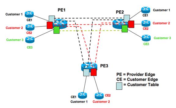
Figure 4 MPLS VLAN
It is also possible for customers to create their own VPN using IPsec. In this case customer, rather than service provider, creates a secure end-to-end path through the public internet. IPsec is used extensively to support satellite offices and telecommuters.
SSL/TSL is another mechanism used to provide end-to-end privacy. SSL was originally developed by Netscape to protect web based financial transactions. Because it is built into all browsers many companies are using it, rather than IPsec, to provide remote employee access.
1.2.7 VoIP (Voice over IP)
The PSTN (public switched telephone network) represents over a hundred years of engineering. Packet based telephony has become a serious contender. Rather than traditional circuit switching VoIP uses packet-based communication to deliver two-way real time voice. Voice communication is very demanding. Voice data rate is low by internet standards only 8-64 kbps in each direction. However latency is critical. If packets are delayed more than a few hundred milliseconds voice quality is seriously degraded.
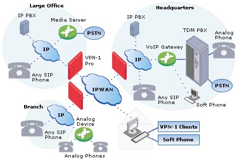
Figure 5 Voice over IP
If the ISP offers VoIP check the service thoroughly. The asymmetric nature of most residential service, upload being much lower than download, makes it easy to saturate the connection. Quality of Service (QoS) may be required to mark VoIP packets, as high priority so they get preferential treatment. Various encoding schemes are used by VoIP that may degrade voice quality compared to traditional phone service. The local Telco that provides our fiber based internet service also provides landline telephone service over the same fiber using VoIP. Over the several years we have had fiber phone service has been fine.
1.2.7.1 Number Portability
In the US the FCC mandates telephone number portability. In most cases you will be able to transfer an existing wire-line or cellular phone number to new service provider.
When we replaced DSL with fiber internet took advantage of number portability to transfer our landline phone number we have had for years. Similarly we have taken advantage of number portability when we have switched cellular providers.
Typically when transferring a phone number you need to contact your current service provider to obtain a security code to prevent Slamming the illegal switching of telephone service.
1.2.7.2 E911
Voice over IP represents challenges for E911 emergency service. Unlike wire-line POTS (plain old telephone service) where telephone location never changes, a VoIP call can originate anywhere. Cellular networks have struggled for years to implement E911 service using triangulation or GPS to locate subscribers. When we moved our landline to VoIP as part of the transition to fiber needed to update location information for 911 response.
1.2.7.3 Fixed Mobile Convergence
There is interest in multimode cellular phones able to utilize both traditional cellular network and opportunistically, WiFi networks. Fixed Mobile Convergence represents a win-win situation for both customer and wireless provider. For providers it utilizes the vast potential of the internet and private LANs to remove traffic from expensive cellular radio networks. For customer it represents potentially lower cost and improved performance. For business it represents a way to eliminate traditional PBX wired telephone infrastructure without paying extravagant per minute charges. Depending on national legal restrictions it may offer arbitrage advantage for multinational corporations to treat voice like email, bypassing local phone companies and eliminating per minute charges.
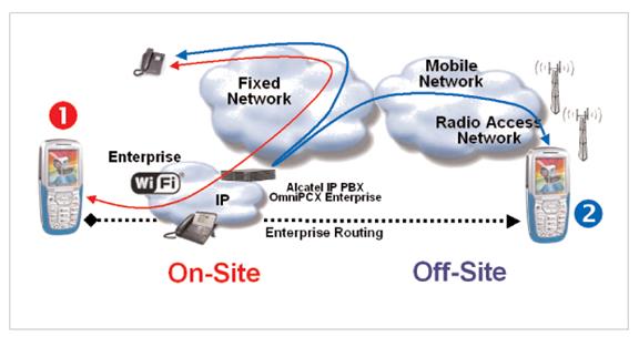
Figure 6 Fixed Mobile Convergence
1.2.7.4 Femtocells
An alternative to WiFi calling is femtocells being offered by several Cellular phone companies. Femtocells are low power cellular base stations that utilize a customer’s broadband connection to deliver coverage to a single home. As with WiFi Cellular providers like it because it moves traffic off cell stations.
Femtocell should not be confused with Cellular repeaters (boosters). Boosters simply amplify radio signals between a cell phone and cell tower. Installation typically involves mounting an outdoor antenna pointed toward the desired cell tower and an indoor antenna located to increase coverage within the residence and not cause interference with the outdoor directional antenna.
WiFi calling is built into our Android phones that is handy here in terrain challenged NH where we have poor cell phone coverage at home.
1.2.7.5 Roaming
A difficult problem is seamless roaming between networks. To a limited extent this is already being done by WiFi as a user moves between Access Points. However for this to work all APs must be under the same administrative control. In an ideal world a device associates with a network and as it moves it automatically reconnects to the best network at the new location seamlessly without any interruption in service. As an example imagine a user beginning a WiFi session at home, gets in their car and moves out of range and is handed off to the Cellular network. They stop for breakfast and are back with range of a different WiFi network, and lastly they arrive at work and now join the corporate LAN. The IEEE 802.21 media independent handover services working group tackled this difficult problem.
1.2.8 IP Television
Over the Air, Cable and DBS TV all use basically the same transmission scheme. RF spectrum is divided into channels. US TV channels are 6 MHz wide, in Europe 8 MHZ. Channels were initially specified to carry a single analog standard definition TV program. Migration to digital transmission allows each channel to carry multiple high definition (HDTV) and/or standard definition programs (SDTV).
IPTV sometimes call OTT (over the top) represents a fundamentally different way to deliver TV leveraging packet-based technology. IPTV opens the door to demand based programming. The traditional broadcast model is one-to-many, an artifact of radio transmission. Once a transmitter is set up anyone within range is able to receive the program. Video on demand (VoD) is like going to the library, rather than changing channels. One simply selects the program of interest and it is delivered virtually instantly anywhere anytime to any device the end user chooses.
Using MPEG-2 compression SDTV requires about 2 Mbps and HDTV 15 Mbps. MPEG-4 yields significantly lower data rates for equal image and sound quality. These rates are the result of spectral (within the picture) and temporal (over time) data compression. Raw data is much too high to be delivered economically.
Video on demand represents many challenges compared to traditional broadcast. Each user is able to start/stop the program at any time requiring a discrete program feed to each user rather than a single feed to all users as with broadcast.
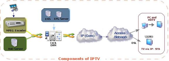
Figure 7 IP TV
Historically residential ISPs assumed a customer traffic model of primarily bursty download traffic such as loading web pages or accessing email. Streaming video and to a lesser extent streaming audio lock up significant bandwidth for extended periods of time. This is much more demanding than browsing.
IPTV dramatizes the disruptive nature of the internet. Since the end of WWII Cable companies have wired areas to deliver broadcast TV over coax and more recently hybrid fiber coax networks. The Cable network is intimately bound to TV delivery. As residential broadband speed increases the door opens for new providers to bundle content and deliver it without the need to either build or own the means of local delivery.
1.2.9 IP Radio
ISPs do not appear much interested in becoming content aggregators for radio the way they are for TV. But other than much lower bandwidth the requirement for internet radio is not much different than internet TV. Many broadcast FM stations also have a streaming service. Radio-Locator is a convenient way to find radio stations.
1.3 Content Delivery Network (CDN)
Basic to the design of the internet is the notion of direct end-to-end communication. When Computer A wants to exchange data with Computer B routers between the two move packets the most efficient way they can on a packet by packet basis. The popularity of streaming video services like YouTube and Netflix stresses the network as millions of users access the same content from diverse locations.
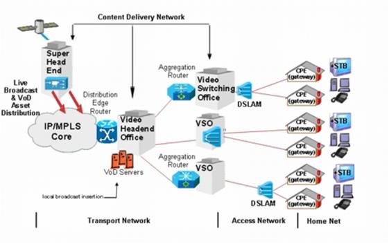
Figure 8 Content Delivery Network
Video is very bandwidth intensive. Video on demand requires a one-to-one connection between user and server as opposed to the one-to-many model of traditional broadcast. Being demand based each user may be viewing a different program or different time within the same program. To address the interest in VoD (video on demand) specialized service providers called CDN (Content Delivery Network) have become popular. The CDN replicate programs on many caching servers and locates them near the ultimate end user. Often they have special peering arrangements with large ISPs or are located within the ISP’s data center itself. CDNs reduce the amount of traffic flowing over internet transit network because they are able to source the file near where it is being viewed. When a customer requests a particular program the ISP’s DNS servers return the address of the local caching server to most efficiently stream the program to the customer.
1.4 Connection Sharing
Historically when a customer contracted with an ISP they were given a block of IP addresses large enough to meet their needs. The IPv4 address shortage forced ISPs to rethink how they allocate addresses. Most residential broadband ISPs restrict customer to a single IPv4 address. This creates a quandary; how to cost effectively connect multiple hosts to the internet? The most common workaround is NAT (Network Address Translation) coupled with use of private IP addresses. RFC 1918 reserves three blocks of IP addresses guaranteed not used on the internet. Because these addresses are not used on the public internet they can be reused multiple times.
Combining NAT, more properly Network Address Port Translation since both address and port number are modified, and private addresses allow a virtually unlimited number of computers to share an internet connection even though the ISP only provides a single address. NAT provides translation between private addresses on LAN and single public address issued by ISP on WAN.
NAT only affects non-local communication. When a request cannot be serviced locally it is passed to the NAT router, called a gateway. The router modifies packets by replacing private address with public address issued by ISP and if needed modifies port number to support multiple sessions and calculates a new checksum. The router sends the modified packet to remote host as-if-it-originated-from-the-router. When router receives the reply the modifications are reversed and the packet forwarded to the originating host. Router tracks individual sessions so multiple computers are able to share a single address. From the internet’s perspective local hosts are invisible. The router looks like a single computer with the address of the public IP issued by the ISP.
IPv6, with its vast address range, does not require NAT. Each device will have its own public IP address. This changes the nature of residential routers. NAT, though not technically a firewall, blocks all incoming connection requests from remote hosts. Unless specifically programmed with port forwarding rules it does not know which device on the LAN to forward the request. This default behavior is lost with IPv6. Residential routers that support IPv6 should block incoming connection requests unless specifically programmed otherwise.
1.5 Carrier Grade NAT
The IPv4 shortage is so severe that some ISP’s are not able to obtain enough public addresses to support their customers. CGNAT works much like end user NAT but uses a different reserved block of IP addresses RFC 6598. In general this is transparent to the customer unless they want to operate a server.
1.6 Blocked Ports
The internet is designed as a transparent end-to-end bit delivery network. This means any host is able to communicate with any other host. TCP/IP and UDP/IP use ports so a host is able to manage multiple simultaneous sessions. Port numbers are 16-bit unsigned values yielding up to 65,535 ports for each connection type. When a service is defined a port number is selected for initial contact. This is called the well-known port. For example the well-known port for HTTP Web access is 80. When a remote user attempts to connect it sends the request to TCP port 80. Once the initial connection is established both computers agree to a use a different combination of ports for ongoing communication. An analogy is to think of well-known port as a doorbell. If ISP blocks access to well-known port remote users are unable to connect.
It is common practice for residential ISPs to block incoming port 80 to prevent customers from running web servers, port 25 to send email to prevent spam, and ports 137, 138, 139, and 445 to prevent remote access to Windows LAN based SMB file sharing. In an effort to reduce file trading some ISPs throttle or block ports used for peer-to-peer file trading applications. Impact of blocked ports varies.
To get around blocked port it is easy to reconfigure the server to use a non-standard port. If access is limited to a small group of friends it is easy enough to simply inform everyone which port to use. If goal is wider public access use of nonstandard ports is a problem. Without knowing the port number remote users are unable to connect. URL forwarding is a technique to work around this restriction.
1.7 Traffic Shaping
The internet is as an egalitarian best effort network. This means as packets arrive they are processed on a first come first serve basis. With enough channel capacity incoming packets never have to wait.
Residential ISPs make assumptions about typical customer usage when they set monthly charges and designed infrastructure. Business model assumed bursty data flow predominantly web browsing, email, and occasional file download. Proliferation of Peer-to-Peer file trading and streaming video services, such as YouTube and IPTV upset these assumptions. ISPs are struggling to carry more traffic than originally planned.
Some ISPs are responding with traffic quotas. When customer exceeds quota either speed is reduced or additional charge incurred. There have been numerous stories of unwitting customers being billed for thousands of dollars in overage charges on their cell phone data account. On the other hand some ISPs detect undesirable traffic and throttle speed rather than blocking it entirely.
1.8 Usage Caps
ISPs often justify usage based pricing as a way to control congestion; however congestion is a temporal phenomenon having little to do with aggregate usage. Congestion only occurs when instantaneous demand exceeds capacity. As has been well documented usage caps are really being used to generate additional revenue or to protect legacy business models.
The other common complaint is the measuring technique is not very accurate.
1.9 Digital Rights Management
The proliferation of digital media devices and networking is making the traditional media world nervous because digital technology allows rapid lossless copying. From a technology standpoint the DRM (digital rights management) mechanisms used to prevent this have been a spectacular failure and in some cases have actually caused damage to end-user devices.
If you or someone on your network is found to be violating copyright law the owner will notify the ISP and the ISP will in turn notify you of the violation.
1.10 Deep Packet Inspection
Some ISPs use a technique called DPI (Deep Packet Inspection) to determine how customer is using the internet and block or throttle use they deem harmful. DPI can also be used to obtain additional information about customer’s internet usage. This data is of interest to targeted marketing vendors. The use of DPI falls into a grey area of what is and is not acceptable ISP behavior. In addition many governments want to know about what their citizens are doing and press ISPs to track customer usage.
1.11 Latency vs Speed
In the quest for ever-faster speed it is important not to lose sight of the interplay between speed and latency. As an example a truck carrying DVDs exhibits very high speed (bits per second) once it arrives but also high latency because it takes hours or days for the data to arrive. Round trip latency is defined as time it takes a packet to go from source to destination and back again. Factors affecting latency are: connection speed, modem overhead, distance, propagation speed, and network congestion.
Modems operate on “chunks” of data increasing latency because entire block must be processed before being passed to next stage. Data cannot be used until the last bit in the bock is received. Low speed connections such as dialup often use smaller packet size to minimize this effect.
Light travels 186,000 miles per second in vacuum. Optical fiber is somewhat slower about 70% of light in vacuum. A packet traveling the 3,000 from New York to LA takes about 25 ms in each direction. To this one must add delay at each router between source and destination. Normally this delay is negligible but if network becomes congested router must temporally store incoming packets until the outgoing path is free. In extreme cases router will discard packets. When packets are lost upper level protocol either requests retransmission (TCP/IP) or in the case of streaming data (UDP/IP) the receiver has to fake missing data.
Impact of latency is heavily dependent on data type. Interactive use such as gaming and VoIP telephony place stringent demands on round trip latency but do not require much bandwidth. File transfer on the other hand is relatively insensitive to latency but places great importance on speed.
Typical first-hop latency varies due to transmission speed and distance: T1 or FTTP 1ms, Cable/DSL 5-30ms, Dialup 100 ms, Geosynchronous Satellite 500ms. For a more in-depth explanation see “It’s the Latency Stupid.”
1.12 Asymmetric Speed
Many residential ISPs provide asymmetric speed: download is much faster than upload. This is done for technical and business reasons. Asymmetric speed allows ISP to position residential service differently than business and charge higher fee for business class service. With the proliferation of residential fiber symmetric download and upload has become more common.
Low upload speed makes it difficult to run a server or use Voice over IP since upload pipe is easily saturated.
1.13 Measuring Speed
End user LAN is rarely the determinate of internet speed as wired and wireless LAN performance normally exceeds internet access speed. Speed is typically limited by first-mile WAN connection. It can be a challenge teasing out various components of end-to-end performance to see if ISP is working as advertised.
IP transmission splits data into 1500 byte chunks called packets (1-byte = 8-bits). Some of the 1500 bytes are used for network control so are not available for user data. TCP/IPv4 uses 40 (TCP/IPv6 60 bytes) of the 1500 bytes for control. NOTE: this analysis assumes use of maximum size packets. Since overhead is fixed using smaller packet incurs higher overhead percentage. With 40-bytes reserved for control out of every 1500-bytes sent only 1460 are available for data. This represents 2.6% overhead.
Some ISPs, typically phone companies, use a protocol called Peer to Peer Protocol over Ethernet (PPPoE) to transport DSL data. This is an adaptation of PPP used by dialup ISPs. Telco’s like PPPoE because it facilitates support of third party ISPs as mandated by the FCC. PPPoE appends 8-bytes to each packet increasing overhead to 48-bytes reducing payload to 1452. Where PPPoE is used overhead is increased to 3.2%.
DSL connections typically use Asynchronous Transfer Mode (ATM) (AAL5) to carry DSL traffic. ATM was designed for low latency voice telephony. When used for data it adds significant overhead. ATM transports data in 53-byte Cells of which only 48 are payload the other 5 are control. Each 1500-byte packet is split into multiple ATM cells. A 1500-byte packet requires 32 cells (32 x 48 = 1,536 bytes). The extra 36-bytes are padded, further reducing ATM efficiency. 32 ATM cells require modem transmit 1,696 bytes of which only 1452 carry payload. Where ATM/PPPoE is used overhead is increased to 14.4%.
TCP/IP overhead 2.6% efficiency 97.4%
TCP/IP/PPPoE overhead 3.2% efficiency 96.8%
TCP/IP/PPPoE over ATM overhead 14.4%, efficiency 85.6%
NOTE: This is best-case speed. Errors, transmission delays, etc. will reduce speed from this value. The higher the speed the greater the impact of even modest impairments on thru put.
It is easy to determine best-case file transfer rate if modem data rate is known. Broadband marketing rate may not the same as modem transfer rate. Some ISP’s set transfer rate higher than marketed speed to compensate for overhead. That way speed test result will be close to marketed speed. Most broadband modems have status page allowing user to observe true transfer rate. This is the rate modem connects to ISP not speed computer connects to modem or router which is typically 10 Mbps, 100 Mbps or 1 Gbps.
By way of example our Fidium fiber internet is marketed as 100/100 Mbps.
Actual speed test result reported bySpeedtest.net shown below.

Figure 9 Speed Test Result
1.14 Speed Optimization
TCP requires receiver periodically send an Acknowledge to let sender know everything is OK. If the transmitter has not received acknowledgement after it sends a number of packets it stops transmitting and waits. This is called the receive window. For high speed connection or where latency is high default receive window (RWIN) should be increased to prevent pauses in transmission. Most modern Operating Systems do a good job optimizing RWIN so little is gained by changing it.
If router supports QoS having it give ACKs priority will improve file transfer rate if upload becomes congested.
The other important tweak is packet size, called the MTU (maximum transmission unit). Maximum packet size is typically limited to1500 bytes. Normally this setting is fine for broadband access, dialup uses a much lower MTU typically 576. PPPoE encapsulation adds 8 bytes to each packet. This reduces maximum packet size to 1492 bytes. If sender attempts to transmit a larger packet it will either be rejected or fragmented into two parts, with attendant performance degradation.
With the available of cheap high speed memory a phenomena called Buffer Bloat, unnecessarily large buffers in network routers. The large buffers result in overly long queuing delays when the network is congested.
1.15 Load Balancing vs Bonding
If one link is not able to deliver adequate speed the obvious solution is to add links. There are two ways to manage multiple links load balancing and bonding.
With load balancing a router with multiple WAN ports is used to share the load. As connection requests come into the router from the LAN it determines which link to use based on link capacity and loading. A given session is constrained by the speed of whichever link it is assigned. Aggregate performance is increased because the router parcels out requests to all the links. A typically web page consists of dozens of separate HTTP sessions to different servers. Load balancing will help in that case. If you are downloading a video load balancing will have no effect.
Bonding is transparent to IP it looks like a single faster pipe. Bonding requires cooperation between the ISP and customer where load balancing can be performed unilaterally by the customer. In the case of DSL bonding is typically performed by the ATM layer that splits data among multiple ATM streams. DOCSIS3 modems do something similar allowing the ISP to allocated more than one channel for internet delivery.
While bonding is able to dramatically improve speed based on the number of connection it has little if any effect on latency. The reason is the modem processing that must occur at each end is the same and even though it is invisible to IP bits need to travel over multiple paths and be reassembled before they are handed off to IP.
1.16 Servers and Dynamic IP Allocation
Most residential accounts are configured automatically each time customer connects. Dynamically assigned IP address makes it difficult to run a server because address may change at any time preventing remote users from connecting until they learn new address. Dynamic DNS service provides a workaround to run servers on dynamic accounts. A daemon runs on either the router or server to detect address changes. When a change occurs it notifies DNS service which in turn automatically updates A records for the site. Even with automatic DNS update there will still a period of time after the address changes where server is not accessible and active sessions are aborted. Dynamic DNS services are really only suitable for casual personal servers, not business use.
1.17 When “Unlimited” Doesn’t Mean “Unlimited”
There has been much press about residential and cellular providers marketing unlimited service and then imposing usage caps or throttling heavy users. Some ISPs have gone so far as to call heavy users bandwidth hogs. The controversy is not about an ISP’s right to set terms of use but rather misleading marketing. It is about calling a service unlimited then throttling or disconnecting a customer if they use it too much.
1.18 When “Always On” Doesn’t Mean “Always On”
Broadband service is marketed as “always on.” Exactly what this means is subject to interpretation. The most “on” service is a bridged or routed connection configured with a static IP address. Once service is configured connection is permanent and always available until the next time the ISP needs to reallocate IP addresses or power fails.
DHCP (Dynamic Host Configuration Protocol) assigns client an IPv4 address for a limited period called a lease at the client’s request. Before the lease expires client attempts to renew. As long as ISP continues to renew the lease the user is never disconnected. From customer’s perspective service is always on, lease renewal is transparent. Some ISPs bind IP address to hardware MAC address. The same IP address is assigned as long as customer does not change equipment. IPv6 uses a somewhat different mechanism DHCP-PD or Router Advertisement but the end result is the same, customer equipment is automatically configured by the ISP.
Point-to-Point-Protocol over Ethernet (PPPoE) or ATM (PPPoA) works like traditional PPP dialup. This type of service is common for ADSL. It leverages ISP investment in RADIUS authentication and billing equipment. Customer provides username/password to authenticate, once authenticated ISP issues an IP address. If connection becomes idle the user is disconnected. Most residential routers include a keep-alive mechanism so connection is never disconnected. From the user’s perspective the connection is always on as long as the ISP is able to maintain an active RADIUS log in session.
Some ISPs limit maximum connect time. After a certain number of hours connection is dropped and must be reestablished. This sort of behavior is common for dialup ISPs and WiFi Hotspots. When connection is dropped customer must log in again to regain internet access.
1.19 Security and Privacy
The internet is a rough and tumble place often likened to the Wild West. The power of worldwide connectivity means anyone on the planet with an internet connection is in a position to attack another connected computer. ISPs often block certain ports to reduce danger to unsophisticated users. Port blocking is a double edge sword as it may interfere with a customer’s legitimate use of the internet. Some ISP's go further acting as a firewall protecting customer from hostile attack and examining email for dangerous content or attachments. Some users consider this a great feature in the battle against spam and viruses. Others see it as an unwelcome intrusion in what should be individual control of network access.
The ISP is privy to all traffic that flows through its system. This raises two concerns, nosey ISPs and subpoenas. The ISP can monitor how customers use the internet, what sites they go to, what email they send and receive and in some cases even snoop usernames and passwords if they are sent in the clear. Even if the session itself is encrypted the to/from destinations have to be visible for the internet to function. Privacy concerns have been exacerbated recently with expanded government snooping due to war on terrorism. US government asked ISPs to provide information about customer internet usage without a court order and in most cases ISPs complied. Internationally governments are mandating ISPs retain customer traffic information for years. The EU has pretty stringent privacy policy but at the same time wants ISPs to maintain long term customer usage records to facilitate law enforcement.
ISP’s privacy policy determines how customer information is used and protected. It is reasonable to expect ISP to collect and use information for diagnostic purposes and to improve service. However, some ISPs sell or otherwise make use of customer’s browsing data, for example as a way to create targeted ads.
Popularity of wireless networks raises additional security concerns. In a wired network an attacker must physical connect to the network. With wireless an attacker is able to eavesdrop from some distance away. This is especially worrisome with WiFi hot spots since they are in public places and the integrity of owner is often unknown. When using public Hot Spots one should be careful accessing any resource over a wireless network where passwords are exchanged in the clear. Specifically email as POP/SMTP credentials are sent in the clear. If at all possible use SSL authentication to access email accounts. At home use WPA2 or WPA3 (wireless protected access) with a strong password to protect privacy. IPv6 addressing presents another possible security issue. One of the addressing schemes uses the 48-bit MAC address for the low order bits of the 128-bit IPv4 address. This means hard coded machine MAC address that is normally not visible outside the LAN in IPv4 becomes part of the pubic IP address and remains the same even when connected to a different ISP. A solution to this problem is to have the computer use a random number rather than the MAC address.
Another risk of wireless networks is the attacker is able to record a large number of sessions and then attempt to break encryption at their leisure.
1.20 Network Neutrality
As internet access becomes pervasive there is growing tension between ISP business practices and public policy. Network Neutrality proponents are concerned ISPs will created walled gardens and be in position to favor some companies and disadvantage others. Opponents of Network Neutrality argue ISPs ought to be able to do anything they want with their own network.
The reason I went into so much detail earlier about required and optional ISP services was to identify those services that only an ISP is able to deliver. Network Neutrality ought to insure network transparency is maintained, innovation encouraged and ISP is allowed to offer value add services while being prevented from acting as gatekeeper. The internet’s rapid rise in popularity is the result of its open architecture. Entrepreneurs need to be able to create new business models and interact with customers without requiring permission or cooperation of the network owner.
1.21 Finding an ISP
It can be difficult finding information about local ISPs. First step is contacting your town’s Cable franchise and incumbent telephone company. Many states are participating in the FCC national broadband mapping program to determine broadband availability. In NH the program is called cleverly enough: NH broadband mapping and planning program. NHBMI is working to deliver more accurate and detailed data on a town by town basis and has a speed test to record actual customer speed. The ease of use and data quality varies a lot by state.
2 Dialup - Plain Old Telephone Service
Dialup has come a long way from Bell 103 acoustic modem (circa 1962) operating at 300 bps to current crop of V.90/92 modems (circa 1998) capable of over 50,000 bps. Dialup internet access is available anywhere there is telephone service. It will even work on cellular at very low speed in a pinch. Dialup was extremely popular in the 1980s – 90s and was the introduction for many folks to the internet and prior to that local BBSes (bulletin board systems). Due to the heavy graphics content of web sites today it is painfully slow by current standards. Almost all Dialup ISPs support ITU-T V.90/92 standard. V.90 modems deliver up to 56 kbps (download) over the PSTN. In the US FCC power limitation reduces maximum speed to 53 kbps. V.90 transmission from subscriber to ISP (upload) uses V.34 mode limiting maximum upload speed to 33.6 kbps. If modem cannot connect in V.90 mode it automatically falls back to V.34 mode in both directions with a maximum speed of 33.6 kbps.
V.92 is a minor enhancement to V.90. Upload speed is increased slightly to 48 kbps and implements faster auto negotiation to reduce call setup time. V.44 improves compression of reference test data to 6:1 vs 4:1 with V.90. Compression increases apparent speed because it reduces the number of bits transmitted over slow telephone network. Modem on Hold (MOH) allows modem to park a data session allowing user to answer a short incoming call. This works in conjunction with Phone Company Call Waiting feature and requires support from the ISP.
|
Figure 10 V.90/92 Dialup Modem End-to-End |
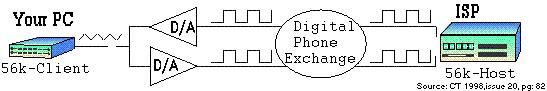
V.90/92 requires ISP modem connect to phone company digital trunk. Only a single digital to analog conversion can exist between ISP and user. Phone lines are analog between customer and central office or remote terminal. At that point they are digitized at 64 kbps. This means POTS modem technology has reached its theoretical maximum speed. To obtain higher speed requires use of different technology.
At connect time modem probes phone line to determine noise and attenuation characteristics in order to set initial connect speed. Speed is constantly adjusted in response to varying line conditions. To obtain maximum speed V.90 and V. 92 modems require phone circuit that exceeds minimum FCC requirements.
2.1 Dial Up Networking
DUN (Dialup networking) is used to establish an internet connection. The most common method used to traverse the telephone network is via PPP (Point-to-Point Protocol). PPP allows internet protocol (IP) packets to traverse the serial point-to-point telephone link between user and ISP. DUN automatically dials ISP phone number, waits for remote modem to connect and establishes a PPP session. The ISP performs user authentication and assigns an IP address. DUN monitors the connection and notifies user when it disconnects.
2.2 Session Duration
Dialup ISP business model assumes customer will stay connected for relatively short periods of time. To enforce this most dialup ISP’s automatically disconnect customer when time limit is reached. Session will also be dropped due to extended inactivity.
2.3 Multilink
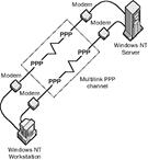
In the quest for higher speed some dialup ISPs support Multilink. Multilink binds two dialup links into a single faster connection. If customer typically connects at say 44 kbps multilink doubles speed to 88 kbps. Multilink requires two modems; two phone lines, and an ISP that supports it. Where available it is a useful technique to obtain better performance from dialup.
![]() Software at each end
of the link splits data between each connection effectively doubling speed.
Unfortunately because data is still traveling over low speed dialup multilink
does not improve latency.
Software at each end
of the link splits data between each connection effectively doubling speed.
Unfortunately because data is still traveling over low speed dialup multilink
does not improve latency.
Multilink is also used with ISDN to bind the two bearer channels together yielding a 128 kbps connection.
2.4 Impairments
2.4.1 Slower Than Expected Speed
Modem data connection is more demanding than voice. There are many reasons for slow dialup even though phone sounds normal. Dialup modem impairments are discussed at length in a separate paper.
2.4.2 Call Waiting
Call waiting generates an alert tone to inform the user someone else it attempting to call. The call waiting process interferes with an existing data call. Call waiting can be temporally disabled at the beginning of a call. The sequence varies by locale, in our area it is *70. Unfortunately sending the disable sequence to a line not equipped with call waiting is interpreted as part of the dialed number, resulting in an incorrect connection. This is a problem if the modem uses multiple lines and not all are equipped with Call Waiting.
2.4.3 Shared Phone Line
If dialup modem shares a phone line with telephone or fax machine there is possibility of mutual interference. If modem is in use picking up a phone will cause modem to disconnect. Conversely if phone is in use modem may attempt to connect interfering with call. One can use a privacy device that monitors phone line voltage to prevent this. When phone is idle open circuit voltage is high around 48 volts, when a phone/modem is in use voltage drops to less than 10 volts. Privacy adapters measure line voltage to prevent phone use if a call is already in place. There are a couple of inconvenient side effects to this approach. Privacy device prevents calls being transferred from one phone to another and it confuses the line use indicators built into many phones. I designed a Modem Access Adapter to prevent interference when modem and phone share the same line.
2.5 Installation
Other than requiring a V.90/92 modem there is no installation. PCs, especially laptops, used to include a built in dialup modem. With the advent of Ethernet and WiFi that is typically no longer the case and will need to purchase a dialup modem and connect it to the phone line. Once that is done create a DUN profile and log into the ISP.
2.6 Life in the Slow Lane
Dialup has the advantage of being accessible anywhere there is a landline phone. It can even be shared by multiple users on a home LAN. For several years in the late 90’s I shared a dialup connection on our home LAN, first using a connection sharing program and later a router. The problem with dialup is its incredibly low speed compared to other forms of internet access. A couple of decades ago, before web sites became so graphics intensive and software programs become chatty and need multi megabyte patches, dialup worked surprising well for our family. Today it is excruciating slow.
3 T-1 and E-1 Digital Carrier
The US Bell System developed T-1 digital carrier during the early 60’s to reduce interoffice transmission cost. Prior to T-1 analog frequency division multiplexing (FDM) was used to carry voice traffic between telephone switching centers. FDM carrier used a 4-wire circuit to carry 24 voice channels, one pair in each direction. T-1 was designed to also carry 24 voice channels, facilitating transition from FDM to TDM. E-1 digital carrier, used in Europe, is similar transporting 30 voice channels. Each voice channel is digitized resulting in a 64 kbps data rate. 24 channels require 1.536 Mbps plus an 8 kbps control channel resulting in data rate of 1.544 Mbps (E1 is 2.048 Mbps). T-1 has a DS-1 channel speed of 1.544 Mbps and is carried over a 4-wire copper facility. Popular usage has corrupted this distinction. T-1 is now commonly used to mean any 1.544 Mbps service.
In the early 1980’s T-1 was tariffed and made available to customers. T-1 continues to be used in commercial service carrying both voice and data but has fallen out of favor due to high price and low bandwidth.
3.1 Converting Voice to Digital Bits
Voice grade phone service occupies the frequency band of 300-3000 Hz. Low frequencies are suppressed to minimize interference from 50/60 Hz power lines. Increasing upper frequency beyond 3000 Hz does little to improve intelligibility, at the expense of greater bandwidth. Digital sampling must be performed at least twice the highest frequency of interest to recover the original analog signal. Engineers chose a sample rate of 8,000 times a second. It was found sampling to 12-bits, resulting in 4096 possible values, produced excellent voice quality. This required 96 kbps per channel resulting in a composite data rate that exceeded what 1960s technology could deliver. To reduce data rate engineers decided to use only 8-bits or 256 values per sample, resulting in a 64 kbps data stream. To minimize quality degradation, conversion is performed logarithmically. When sound level is low samples are close together. During loud passages samples are farther apart. This masks quantizing noise generated by the conversion process. Two slightly different methods are used, µ-law in US and A-law in Europe. The resulting digital signal is called Pulse Code Modulation (PCM). 24 phone calls in US (T-1) or 30 Europe (E-1) are interleaved using Time Division Multiplexing TDM combined with an 8 kbps signaling channel the composite data stream is 1.544 Mbps (US) or 2.048 Mbps Europe.
PCM coding scheme developed for T-1 is what makes V.90 and V.92 dialup modems possible and also the reason dialup is limited to 56 kbps.
3.2 Channelized vs. Unchannelized
When used for internet access voice channelization is neither required nor desired. In that case T-1 data circuits are unchannelized exposing total channel capacity to the IP layer. IP, rather than T-1, performs multiplexing. Some circuits are provisioned to allow flexible control of channelization. This allows an Integrated Access Device (IAD) to dynamically allocate bandwidth between voice and data.
3.3 Provisioning
The original implementation of T-1 required regenerators spaced every 6,000 feet. Regenerators recreate bipolar signals, allowing T-1 to deliver very low error rates compared to analog carrier. Regenerators can be powered from the T-1 line, called a span, eliminating need for local power. T-1 bipolar signaling is relatively noisy. This requires care during circuit provisioning to prevent interference between T-1 and other services, including other T-1s and DSL in the same cable.
Early T1 required a 4-wire circuit, 1-pair in each direction. Newer T1 deployments using HDSL2 only need a single pair. Digital signal processing techniques similar to that used with DSL reduce outside plant cable requirement and increases distance between regenerators.
4-wire T-1 circuit can be up to 50 miles, with regenerator every mile. Very long T-1 circuits are rare nowadays as fiber is more cost effective.
3.4 CSU and DSU
Channel Service Unit (CSU) is connected directly to the 4-wire facility. The CSU regenerates T-1 bipolar signals before handing them off to Data Service Unit (DSU). The CSU provides keep alive and Loopback testing enabling Telco to monitor line quality.
T-1 uses bipolar plus and minus 3-volt pulses, between pulses line voltage returns to zero. The Digital Service Unit (DSU) converts bipolar signals to a synchronous interface such as V.35 using both RS232 single ended and RS422 differential signaling to connect to customer equipment.
In the US CSU and DSU are built into customer premise equipment (CPE), such as a T-1 router. In the rest of the world CSU is owned by service provider, CPE includes only the DSU.
3.5 Smartjack
 When T-1 was developed the interface between CSU and
DSU, called DSX-1, was designated the demarcation point between Telco and
customer. DSX-1 is still the demarcation point in rest of the world. During US
deregulation the FCC defined the 4-wire facility as the demarcation point. This
caused problems for service providers as now management and quality assurance
functions were no longer under their control but provided by customer premise
equipment (CPE).
When T-1 was developed the interface between CSU and
DSU, called DSX-1, was designated the demarcation point between Telco and
customer. DSX-1 is still the demarcation point in rest of the world. During US
deregulation the FCC defined the 4-wire facility as the demarcation point. This
caused problems for service providers as now management and quality assurance
functions were no longer under their control but provided by customer premise
equipment (CPE).
![]() The solution was
the Smartjack. It presents a 4-wire (2-pair) interface to customer and
implements service provider Loopback test function. This allows Telco to
perform testing and maintenance functions while complying with FCC regulations.
The solution was
the Smartjack. It presents a 4-wire (2-pair) interface to customer and
implements service provider Loopback test function. This allows Telco to
perform testing and maintenance functions while complying with FCC regulations.
Smartjacks can be also used to deliver T-1 service to customers by converting other transmission schemes to traditional 2-pair T-1 such as fiber.
3.6 Installation
The service provider will typically install the Smartjack within a few hundred feet of where drop cable enters the building. Customer needs to purchase a router and install it. The cable between CPE and Smartjack is a regular Category rated patch cable.
3.7 Beyond T-1
The wired telephone network is almost entirely digital except for the 2-wire analog POTS customer loop. With digital technology multiple voice channels can easily be carried over a single circuit. The digital carrier hierarchy is based on voice channels. The lowest level, called Digital Service 0 (DS-0), is a single PCM digitized voice circuit of 64 kbps. Next is DS-1 (24 voice circuits over T-1 carrier) operating at 1.544 Mbps, then DS-2 (T-2) operating at 6.312 Mbps equivalent to 4 T-1 circuits, then DS-3 (T-3) at 44.736 Mbps equivalent to 28 T-1 circuits.
Higher speed is optical using SONET (Synchronous Optical Network) and ITU SDH (Synchronous Digital Hierarchy). Optical Carrier 1 (OC-1) and Synchronous Transport Signal Level 1 (STS-1) operate at 51.84 Mbps, next is STS-3 (OC-3) 155.52 Mbps, then STS-12 (OC-12) operating at 622.08 Mbps and so forth. Beginning with STS3 hierarchy increases by a factor of four at each step. 10G bps STS-192 (OC-192) is an interesting convergence point. It is the first time Ethernet and SONET/STS operate at the same speed opening the door for Ethernet being carried directly over SONET.
|
Telco Digital Carrier Hierarchy |
||
|
Line Rate |
Designation |
Notes |
|
639.009 Gbps |
OC-12288 STM-4096 |
|
|
159.252 Gbps |
OC-3072 STM-1024 |
|
|
100 Gbps |
|
100 Gig Ethernet (not part of digital hierarchy) |
|
39.812 Gbps |
OC-768 STM-256 |
Telco convergence 40 Gig Ethernet |
|
10 Gbps |
|
10 Gig Ethernet (not part of digital hierarchy) |
|
9.953 Gbps |
OC-192 STM-64 |
Telco convergence 10 Gig Ethernet 10G-PON/EPON down |
|
4.977 Gbps |
OC-96 |
10G-PON up |
|
2.5 Gbps |
|
2.5 Gig Ethernet (not part of digital hierarchy) |
|
2.488 Gbps |
OC-48 STM-16 |
G-PON Down |
|
1.244 Gbps |
OC-24 |
G-PON Up, E-PON dn/up, 10G-EPON up |
|
1 Gbps |
|
Gig Ethernet (not part of digital hierarchy) |
|
622.080 Mbps |
OC-12 STM-4 |
B-PON Downstream |
|
155.520 Mbps |
OC-3 STS-1 |
B-PON Upstream |
|
100 Mbps |
|
Fast Ethernet (not part of digital hierarchy) |
|
51.840 Mbps |
OC-1 |
Base of the optical hierarchy |
|
44.736 Mbps |
T-3 DS-3 N.A. |
|
|
34.368 Mbps |
E-3 Europe |
|
|
10.000 Mbps |
|
Ethernet (not part of digital hierarchy) |
|
8.448 Mbps |
E-2 Europe |
|
|
6.312 Mbps |
T-2 DS-2 N. A. |
|
|
2.048 Mbps |
E-1 DS-1 Europe |
30 DS-0 voice channels |
|
1.544 Mbps |
T-1 DS-1 N. A. |
24 DS-0 voice channels, Primary Rate ISDN |
|
144 kbps |
Basic Rate ISDN |
2B (DS-0 bearer channels) + D (16 kbps data channel) |
|
64 kbps |
Digital Signal-0 |
Single 64kbps PCM voice channel |
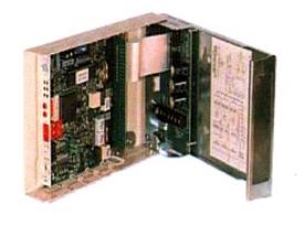
4 ISDN - Integrated Service Digital Network
![]() Tremendous
success of T1/E1 prompted the Telephone industry to look for a way to deliver
high-speed digital service directly to customer. Integrated Service Digital
Network (ISDN) was
supposed to be the next big thing poised to revolutionize the telephone
industry. Alas things have not played out that way. Deployment missteps and
high cost have relegated ISDN as a technology footnote.
Tremendous
success of T1/E1 prompted the Telephone industry to look for a way to deliver
high-speed digital service directly to customer. Integrated Service Digital
Network (ISDN) was
supposed to be the next big thing poised to revolutionize the telephone
industry. Alas things have not played out that way. Deployment missteps and
high cost have relegated ISDN as a technology footnote.
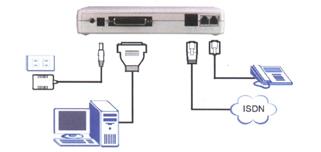
Basic rate ISDN provides two 64 kbps bearer channels (B channels), and a 16 kbps data control channel (D channel) over a single voice grade copper loop. Primary Rate ISDN is basically a T-1 connection. ISDN is a circuit switched technology with very fast call setup time. Being digital full 64 kbps is available. ISDN requires a Terminal Adapter (TA). The TA connects to ISDN copper loop, provides two POTS analog phone lines, and a serial data connection.
4.1 Dial Up Networking
ISDN is a circuit switched technology. To access the internet a phone call is made to the ISP, just as with analog dialup. Once connected access speed is 64 kbps due to the end-to-end digital nature of the connection. If the ISP offers multilink the second channel can be bonded to create a 128 kbps link. Extra channel can be automatically torn down and set up as needed to free up capacity for voice call.
4.2 Installation
I don’t think there are any telephone companies still offering ISDN
5 DSL - Digital Subscriber Line
DSL (Digital Subscriber Line) technology utilizes telephone copper wiring between subscriber and Phone Company CO (central office) or RT (Remote Terminal) to deliver high-speed data. This allows LEC (local exchange carrier) to generate additional revenue by leveraging its massive investment in copper outside plant cabling. Several types of DSL have been developed hence the xDSL moniker. The most common types are Asymmetric DSL (ADSL) G992.1, ADSL2 (G.992.3), ADSL2+ (G.9925) and Symmetric DSL (SDSL). Telco’s like DSL not only as another revenue source but because it gets long duration data calls off the Public Switched Telephone Network (PSTN). This minimizes need for expensive upgrades to circuit switched phone network. In the early days of consumer broadband I thought DSL would win as it does not require changes to outside plant. Unfortunately the attenuation of copper loops severely constrains speed.
ADSL was initially developed for video on demand and has been repurposed for internet access with higher download speed, toward the subscriber, than upload. It uses frequencies above those used for Plain Old Telephone Service (POTS) allowing it to coexist with voice service. This minimizes cost by allowing a single copper pair to be used for both voice and data. Maximum ADSL2 speed is about 12 Mbps down and 1 Mbps up.
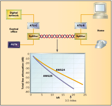
![]() The DSLAM (Digital Subscriber Line Access Multiplexer) at the
Telephone Central Office or Remote Terminal is connected to the customer’s
phone line. The voice portion is passed through a low pass filter and delivered
to POTS phone switch. The DSLAM recovers customer data and uses ATM to link
customer to ISP. Telco’s use ATM because it facilitates support of third party
ISPs. At the customer location a similar filter is used to separate high
frequency DSL from POTS. This can be a single whole house POTS/DSL splitter or an
inline filter connected ahead of each non-DSL device.
The DSLAM (Digital Subscriber Line Access Multiplexer) at the
Telephone Central Office or Remote Terminal is connected to the customer’s
phone line. The voice portion is passed through a low pass filter and delivered
to POTS phone switch. The DSLAM recovers customer data and uses ATM to link
customer to ISP. Telco’s use ATM because it facilitates support of third party
ISPs. At the customer location a similar filter is used to separate high
frequency DSL from POTS. This can be a single whole house POTS/DSL splitter or an
inline filter connected ahead of each non-DSL device.
Maximum DSL speed is a function of line length, wire gauge and line quality. ADSL service is limited to about 18,000 feet, with closer customers able to obtain higher speed. A variant of ADSL2 called Reach Extended adds a couple thousand feed at low speed. Remote DSLAMs, called RT (Remote Terminals), shorten loop distance by moving the DSLAM closer to the customer. This increases number of potential customers within range and shorter loop increases maximum speed.
|
Figure 15 ADSL First-Mile |
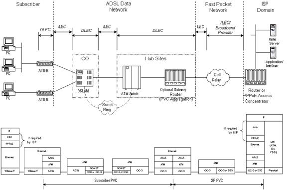
FCC regulations require Incumbent ILEC (Local Exchange Carrier) allow third party CLEC (competitive local exchange carrier) access to copper subscriber access network. Copper subscriber loop is tariffed as an unbundled network element (UNE). CLECs rent collocation space within the central office and install their own DSLAMs and backhaul facilities. Even ILECs need to set up a separate business entity to deliver DSL because unlike phone service data is not a regulated service.
5.1 VDSL vs ADSL
VDSL2 is a high speed variant of ADSL using the same Discrete MultiTone (DMT) modulation scheme to transmit data in the 100 Mbps range over short loops. It accomplishes this by using many more tones resulting in a much higher upper frequency. VDSL2 is the preferred method to deliver fiber to the curb (FTTC) and is often used to convert fiber for distribution in multitenant buildings.
5.2 Splitter vs Inline Filter
ADSL and Voice telephone share a single copper circuit. At each end filters prevent high frequency DSL signals from interfering with voice phone. To reduce cost ADSL service providers include inline filters as part of a customer self-install kit. Customer is instructed to installed filter at each non-DSL device. Having customer self-install filters eliminates expense of a truck roll.
An alternative to per device filtering is a whole house POTS/DSL splitter. Splitter provides low pass filter isolating voice from high frequency DSL tones. Splitter has two outputs; “Data” connected directly to DSL modem and “Voice” connected to inside phone wiring. Some splitters contain a half-ringer test circuit after the low pass POTS filter. This allows removal of half-ringer in NID, minimizing DSL signal loading. Splitters do a better job isolating DSL from voice then inline filters. Where speed is high or signal is marginal a splitter will improve margin.
|
|
|

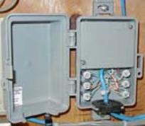
Figure 16 Inline Filter and Whole House POTS/DSL Splitter
|
Splitter Advantage |
Splitter Disadvantage |
|
|
5.3 Interleave vs Fastpath
DSL lines are susceptible to noise bursts from many sources such as: lightning, ignition noise, radio transmissions and power line faults. DSL spec writers were aware of this and included FEC (forward error correction)). FEC adds redundant check bits to data stream. If noise corrupts data these extra bits are used to recover the data. As long as only a few bits are damaged receiver is able to correct errors avoiding need for retransmission.
If noise burst is long it corrupts too many bits for receiver to undo damage. In that case bad packet is passed to higher layer protocol, then TCP requests retransmission. Needless to say that takes a "long time.” UDP/IP, used with VoIP and streaming data does not have a retransmission scheme as there is not enough time to retransmit data before it is needed by application. Streaming applications have provisions to fake missing data. How bad missing data affects quality depends on the application and how extensive the damaged.
When interleave is turned on bits from several frames are interleaved in time. If noise burst is long relative to bit time it corrupts many bits. When receiver deinterleaves data corrupt bits are now spread across multiple frames - increasing chance FEC is able to correct them. This eliminates need for retransmission or application having to fake missing data.
As speed increases number of bits affected by a given noise burst increases. Let’s say a noise burst corrupts a single bit at 768 kbps. At 1500 two bits and at 3000 the same pulse affects four. In addition as transmission speed increases signal to noise margin decreases making transmission more susceptible to noise corruption.
Downside of Interleave is slightly higher latency because multiple frames are processed as a single entity. The penalty for Interleave goes down as speed goes up since a given frame takes less time to transmit at higher speed. Unless you are an avid gamer interested in absolute lowest possible ping time Interleave is transparent. Other network effects swamp out the slight increase (10-20 ms) in first hop ping. Telco’s did not implement Interleave to annoy gamers; they did it to improve overall customer satisfaction.
5.4 Bonding
The ADSL2 specification allows multiple phone lines to be bonded together to obtain higher speed. This is accomplished through an ATM inverse multiplexing protocol. In some instances this may be a cost effective strategy to increase speed.
5.5 Dry Loop
The most common type of ADSL shares the same physical circuit as POTS telephone. The cost of the line is charged to the telephone DSL in effect rides for free. It is possible to get DSL as a standalone called dry loop. In that case the ISP will pass along an addition charge to cover the cost of renting the circuit. In some cases this is not much less than actually having phone service.
5.6 Impairments
DSL uses 100-year old copper telephone network to carry high-speed data. This is an impressive engineering accomplishment. Unfortunately not all phone lines are suitable for DSL. Assuming the local central office (CO) or remote terminal (RT) is equipped for DSL it may not be available for a number of reasons. This section discusses common problems and where applicable workarounds.
5.6.1 Network Interface Device (NID)
In the bad old days before US telecom divestiture (1880’s to early 1980’s) Phone Company supplied service, owned CPE (customer premise equipment) and leased it to customer. Customer was prohibited from connecting anything to the telephone network. With divestiture Phone Company regulated responsibility was limited to delivering service to premise. Inside wiring and CPE became the customer’s responsibility.
This created a dilemma for the Phone Company, how to determine if a problem was their responsibility or that of the customer? Enter the NID (Network Interface Device). NID is the demarcation point, between Phone Company and customer. It incorporates lightning protection and a method to easily disconnect CPE from the telephone network. Early NIDs used modular jack connected to old style carbon block lightning protector. Over time NIDs evolved into an integrated package and gas tube surge protection replaced carbon block. Gas tube protection is preferred because module is hermetically sealed, provides more consistent over voltage protection and has lower shunt capacitance then carbon block. Carbon protectors have to tendency to increase circuit noise over time. This may cause problems if DSL signal is weak.
Phone Company uses automatic test equipment called MLT (mechanized loop test) to periodically test copper phone lines. They wanted a device; built into the NID, which allowed MLT to determine where the network ended and where customer responsibility began. The most common implementation is the half-ringer simulating a phone within the NID. DSL is designed to operate in the presence of this test circuit.
5.6.2 Distance
ADSL service is limited to about 18,000 feet. Some ILECs are installing Remote Terminals (RT) to reduce cable distance allowing them to serve more customers at higher speed. ADSL2 and Reach Extended ADSL2 have slightly extended maximum distance. Obtaining accurate pre order distance estimate can be a difficult. The effective wire distance between DSLAM and customer is often substantially longer than driving distance making map based estimates questionable.
A back of the envelop method to calculated wire distance is to multiple downstream attenuation by 250 to obtain distance in feet. The graph below shows typical downstream speed vs length. The portion at 80-90 dB is extra distance obtained by virtue of ADSL2 Reach Extended option. By way of example I am a DSL customer, my attenuation is 46dB and modem syncs at 7Mbps +/-400kbps with 6-10 dB margin.
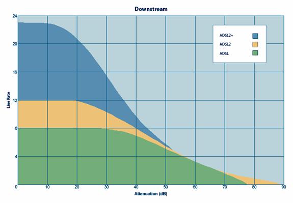
Figure 17 DSL Distance vs Speed
5.6.3 Bridged Taps
When telephone feeder cable is installed it is not known how many customer circuits will be needed at each location. The solution is to run a large feeder cable past many customers. As service is installed the technician selects an unused cable pair and splices it to the drop cable. The circuit feeding the drop may continue for hundreds or thousands of feet beyond the customer, resulting in a bridged tap. Bridged taps are of no consequence for telephone service but can degrade DSL. The presence of a bridged tap causes DSL signal to split at the tap going down both paths. When it reaches the end it is reflected back into the line, creating interference. DSL is designed to tolerate some amount of bridged tap, but if circuit is marginal it may cause problems or push customer over distance limit. SDSL providers typically pay Telco to remove bridged taps. This is expensive and is not ordinarily done for low cost residential ADSL.
5.6.4 Load Coils
 Resistance and impedance attenuate
signals. This effect is more pronounced at high frequencies and long circuits. Load coils are used on long
loops to cancel these harmful effects resulting in better voice
characteristics. Load coils are typically installed on loops over 18,000 feet.
H88 load coils, the most common type, are spaced every 6,000 feet beginning
3,000 feet from the central office.
Resistance and impedance attenuate
signals. This effect is more pronounced at high frequencies and long circuits. Load coils are used on long
loops to cancel these harmful effects resulting in better voice
characteristics. Load coils are typically installed on loops over 18,000 feet.
H88 load coils, the most common type, are spaced every 6,000 feet beginning
3,000 feet from the central office.
![]() Unfortunately load
coils are incompatible with DSL. They flatten response over the voice frequency
range but severely attenuate high frequencies used by DSL. If Load coils are
present they must be removed.
Unfortunately load
coils are incompatible with DSL. They flatten response over the voice frequency
range but severely attenuate high frequencies used by DSL. If Load coils are
present they must be removed.
5.6.5 Loop Carrier
Digital Loop Carrier (DLC), Digital Added Main Line (DAML) et al are techniques to allow multiple telephone customers to share a single copper circuit. Phone companies use loop carrier when there are no available physical circuits and in rural areas where cost of active electronics is less than running a dedicated circuit to customer. Unfortunately most forms of DLC are incompatible with DSL.
5.6.6 Noise and Crosstalk
Telco feeder cable carries many different services: POTS, ISDN, DSL and T-1. Phone circuits often closely parallel power lines picking up power line noise. Imperfections cause unintentional coupling from one circuit to another. This raises the noise floor. If noise becomes excessive speed is impacted.
Residential DSL is not typically warranted for speed, it is a best effort service. If noise is present during phone call customer is more likely to get problem resolved than if it only affects DSL or dialup.
5.6.7 Backhaul Congestion
Much advertising ink has been spilt stating DSL is not shared. While that is certainly true all internet connections are shared at some point, the issue is where and will it affect service. With DSL the chokepoint is backhaul from the DSLAM, especially in the case of remote terminals. If backhaul becomes congested all user of that DSLAM will suffer.
5.7 Safety
Copper phone circuit is able to carry not only telephone and internet but dangerous voltages. This may occur due to nearby lighting strikes or accidental connection between power line and phone. One of the functions of the NID is to protect people and equipment from hazardous voltages. Older installation use carbon block protector while newer use hermetically sealed gas tube. Both have the same function, when exposed to excessive voltage they short the phone line to ground.
5.8 Installation
Assuming you already have a landline most residential ADSL is self-install, the ISP sends out an ADSL router and several inline filters. Filters need to be connected to each non-DSL device and the modem located in a convenient place. Connect modem to PC with an Ethernet cable and plug modem into phone jack. Most ISPs use PPPoE that requires customer enters a username and password. To support more than one device one needs to use a DSL router. In many cases the router has a walled–garden mode until it is configured that walks the customer through the required steps. If router includes WiFi that will also need to be configured as well as any devices that use it.
If this is dry loop or there is no phone at the location the ISP will need to work with the local exchange carrier to install a drop. It is the customer’s responsibility to perform inside wiring to connect the NID to the DSL modem.
Since DSL is fairly short range telephone load coils are normally not present but if they are will need to be removed.
Our first foray into the world of DSL was SDSL at 512/512 kbps however that company went bankrupt shortly after we signed up. During the time we had DSL and landline phone it was supplied by the local phone company and then moved to a CLEC in to get faster speed.
6 FTTC - Fiber to the Curb
VDSL2 is optimized for very high-speed service over short telephone loops. Think of VDSL as ADSL on steroids. It uses the same DMT modulation as ADSL but many more tones extending the upper frequency range to 10s of MHz The sweet spot for VDSL2 is 50 Mbps @3,000ft. To deploy VDSL carriers are building FTTC (fiber to the curb) networks. Several Telco’s have opted for this approach but it has not been well received for a number of reasons. One area that has seen more success is in MDU (multi-dwelling units). The carrier brings fiber to the building and then uses existing phone grade copper wiring within the building to connect individual tenants.
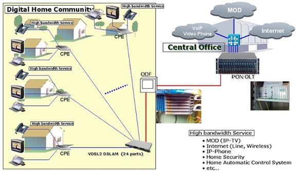
Figure 19 Fiber to the Curb
6.1 Impairments
Impairments are the same as for ADSL, but due to the much higher frequencies everything is much more critical.
6.2 Installation
Installation is much the same as ADSL.
7 DOCSIS - Data Over Cable Service Interface Specification
Cable TV (CATV) industry started in the 1950’s as Community Access TV in areas where roof top antennas did not provide adequate reception. Early pioneers found they could locate a large antenna on a local mountaintop and distribute broadcast TV over coaxial cable. By the 1990’s the industry was looking for new revenue streams and ways to fend off inroads being made by DBS (Direct Broadcast Satellite) and Telco DSL.
Historically Cable TV has been a one-way medium. TV signals originated at the CATV HE (Head End) and were delivered to subscribers over coaxial cable. To accommodate internet service the Industry needed to upgrade unidirectional one way “broadcast” cable distribution with a bidirectional system. This involved replacing distribution amplifies with bidirectional amps. Previous upgrades had modified the coaxial network with Hybrid Fiber Coax (HFC). Fiber is deployed deep into the CATV network. Redundant fiber loops interconnect the Head End to hubs. The hubs in turn connect to local nodes that convert fiber to coax. Coax is only used for relatively short distance connecting individual subscribers to HFC network.
|
Figure 20 HFC Distribution Network |

Cable Labs, an industry consortium, developed DOCSIS to deliver two-way internet service over the HFC CATV network. Like the IEEE Ethernet spec DOCSIS has evolved over the years to provide higher and higher data rates.
Cable is a shared network; to prevent eavesdropping and attachment of unauthorized modems DOCSIS encrypts traffic in both directions.
CATV is typically thought of as a residential service. CATV industry is actively courting commercial customers. High speed and low cost makes Cable based internet access an attractive alternative to expensive T-1 service.
|
Figure 21 DOCSIS Architecture |
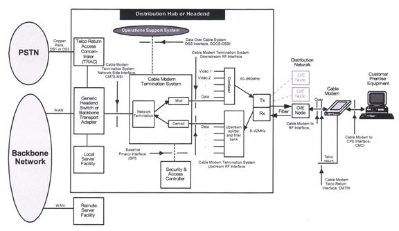
7.1 Impairments
The CATV network, much like the phone network, it has been pressed into service to deliver high speed internet connectivity. There are a number of issues that interfere with obtaining maximum possible speed.
7.1.1 Shared Medium
Cable is a shared medium. Each user competes with others on the same segment. While all internet access is shared at some point Cable is shared in the first-mile. As more customers subscribe Cable provider, called MSO (Multi System Operator) must reduce number of subscribers per segment to deliver acceptable service. MSOs are aggressively driving fiber deeper in their outside plant to reduce the number of customers serviced by a node allowing them to offer higher speed.
7.1.2 Limited Upload
DOCSIS uses a time slot mechanism, called TDMA (Time Division Multiplexing Access), to facilitate equitable upload over the shared cable segment. The Cable industry had assumed customers would primarily use download capacity. Customers are taking advantage of internet peer-to-peer capabilities to create and host their own data, use Voice over IP telephone service, and real time video conferencing. This creates a strain on limited Cable upload capability.
There are a number of techniques to increase upload performance. Synchronous Code Division Multiple Access works better in the lower frequency upstream channels unsuitable for Advanced Time Division Multiple Access. Another technique, channel bonding, combines multiple upstream channels to increase performance. The latest DOCSIS specification goes a long way to alleviating the upload problem.
7.1.3 Noise Ingress & Signal Leakage
Cable systems operate up to about 900 MHz much of this range is not authorized for over the air broadcast. This places stringent demands on the cable operator to prevent RF leaking out of the network interfering with radio users or power leaking in interfering with subscribers. Ingress leakage is an especially difficult problem for the low frequencies (below Channel 2) 54 MHz
7.1.4 Signal Level
Cable Company endeavors to maintain adequate signal levels to support both DOCSIS internet access and TV. Common practice is to install a two way splitter where cable enters the residence. One drop is connected directly to the DOCSIS modem, the other to TV. If multiple TVs are used a bidirectional amplifier may be needed to make up for signal loss through the splitter. DOCSIS modem should always be connected to the two-way splitter rather than behind an amplifier.
7.2 Safety
Coax cable, being an electrical conductor, may carry stray currents into the building. NEC requires the shield to be bonded to building ground system to minimize potential shock hazard. Excessive noise or AC hum can degrade both TV and internet access.
7.3 Installation
If Cable has never been installed the MSO will need to install coaxial drop, ground coaxial cable shield where it enters the building and install a splitter. DOCSIS modem connects to one splitter port the other is used to connect one or more TVs. Depending on signal levels and number of TVs the installer may need to install a distribution amplifier.
If premises is already wired for cable all the installer will typically need to do is install a splitter near where the cable enters the building and run a new drop to the modem location.
Because Cable is a shared medium the MSO binds a particular modem to the account. If you need to change the modem will most likely have to contact the cable company to update their information.
8 FTTP - Fiber to the Premise
The holy grail of broadband access is fiber optic service all the way to the customer FTTP. Installing a fiber optic network is about twice as expensive as copper phone and three times that of Cable. Service providers are faced with the difficult business decision of choosing to invest in technology to extend life of their existing network or take the plunge and install fiber. Deploying fiber puts the company in a very strong long term competitive position but demands tremendous up front capital investment. Due to fiber’s incredible bandwidth fiber ISPs are able to offer cost effective telephone landline service and traditional Cable TV using the same fiber.
Fiber is ideal for Greenfield locations. Installing fiber in a new location is cheaper than the combined cost of deploying traditional Copper POTS phone lines and HFC Cable network and results on much lower ongoing maintenance cost.
The high cost of deploying FTTP is an impediment to adoption. Companies are working hard to reduce both labor and equipment cost so as more systems are installed cost is falling. Developments such as fiber optic ribbon cable, preterminated cable assemblies and automated cable fusion splicers reduce deployment cost. Advances in fiber optic cable manufacture reduce the effect of tight bends on optical loss. Bend insensitive cable is ideal for multitenant buildings.
FTTP is able to emulate analog POTS (plain old telephone service) by digitally encoding voice using VoIP. From a subscribers perspective VoIP service is identical to legacy POTS delivered over copper cable with the exception VoIP requires the customer provide local power.
TV programs can also be delivered by emulating the methods used by Cable providers. A third “color” lambda is used to transmit programs from head end to customer. At the ONT the optical signal is converted to RF and delivered over existing coaxial cable to set-top-boxes like those used for Cable. An interesting economic wrinkle as cord-cutting increases, more and more customers are not subscribing to traditional “Cable TV” so many new fiber deployments do not offer traditional “Cable TV.”
Optical networks are well suited for VoD (Video on Demand). Rather than being required to view a program at a certain time VoD allows the customer to watch what then want when they want. VoD requires tremendous network capacity, especially HDTV. Each HDTV program requires about 15 Mbps; SDTV 2 Mbps. FTTP has enough capacity to easily deliver multiple TV programs.
8.1 Point-to-Point Ethernet
With Switched Ethernet a customer is directly connected to a port on the ISP edge router. The advantage of this approach is costly electro/optical interfaces only need operate at the link rate, typically 100 Mbps or 1 Gig rather than the aggregate PON rate. Customer premise equipment is cheaper since it only has to convert a point-to-point optical interface to Ethernet. The down side is much more fiber is required in the field.
8.2 Passive Optical Network
PON uses a single optical fiber to deliver services to 32 or more customers. It has become the preferred deployment method for residential fiber due to its attractive cost due to reduced fiber count. Traffic toward the customer is broadcast to all endpoints. Upstream traffic utilizes a TDM (time division-multiplexing) scheme to insure access fairness. Traffic in each direction is carried by a different color, called Lambdas. WDM (Wavelength Division Multiplexing) allowing a single fiber to carry traffic in each direction without interfering with one another. Convergence points contain passive optical splitters to connect multiple customers to a single trunk fiber. PONs also has the advantage is it does not require active electronics in the field. To protect privacy optical traffic is encrypted.
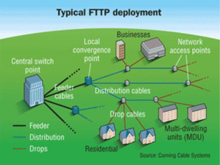
Figure 22 PON Outside Plant
8.2.1 PONs PONs and more PONs
Both ITU and IEEE Ethernet in the first mile have developed PON specifications. Download speed ranges from a low of 622 Mbps for the first generation ITU standard to 10 Gbps for newer ITU and IEEE versions.
8.2.2 A-PON B-PON
The first generation of consumer PON networks used ATM PON to provide data and voice virtual circuits over single fiber. APON specification delivers aggregate bandwidth 622 Mbps down and 155 Mbps up. Maximum fiber distance is 20 km (65 kft).Broadband PON (B-PON) uses a third optical wavelength to emulate legacy CATV network for triple play service. ATM is used for transport reducing effective IP payload by about 10% due to ATM overhead. One also needs to factor in AAL2 POTS voice channels at 64 kbps each.
1550 nm is used to emulate CATV HFC (Hybrid Fiber Coax) network. In the US TV channels are 6 MHz wide. Each channel can be used to carry a single analog SDTV channel or when digital up to 42 Mbps of data. This enabled a single channel to carry multiple digital SDTV or HDTV programs.
1490 nm is used to transmit data toward the customer. Each ONT “sees” all packets on the cable. However only those destined to the customer are decrypted and forwarded to customer’s Ethernet connection.
1310 nm is used to transmit data from customer to ONL. Upstream traffic is based on a time division-multiplexing scheme to insure fairness. Unused slots are reclaimed and are available to other customers.

Figure 23 B-PON Triple Play
8.2.3 G-PON
The demand of ever higher speed resulted on various versions of GPON ITU-T G984 increased speed to 2.5 Gbps down and 1.25 Gbps up. GPON does away with ATM eliminating so-called ATM cell tax. The higher speed of GPON makes it better suited to IP based video on demand then first generation PON. XGPON ITU-T G987 increased aggregate speed to 10 Gbps down and 2.5 up.
GPON and XGPON have replaced earlier generation of PON for new installs. Two lambdas are used as with B-PON for data download and upload. Optionally a third Lambda can be used to emulate traditional Cable TV. However as previously mentioned due to cord cutting some fiber ISPs no longer offer tradition TV service.
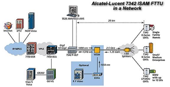
Figure 24 G-PON
8.2.4 E-PON
IEEE Ethernet in the First Mile working group developed an Ethernet version of PON that does away with ATM and delivers Gigabit (1.25 Gbps) speed. E-PON is faster than B-PON (622/155 Mbps) but not as fast as new ITU GPON (2.4/1.2 Gbps).
8.2.5 10G-EPON
Second generation Ethernet PON increases speed to 10/1Gbps with an option for symmetrical 10/10 Gbps. The down side of symmetric 10G-EPON is the need for expensive optical transmitters in the customer ONT.
8.3 MoCA - Multimedia over Coax Alliance
FTTP cable TV emulation is unidirectional – toward customer. This creates a problem for smart set-top-boxes that need to communicate with the head-end. Initially set-top-box required both coax and Ethernet connection. While that is conceptually easy it is labor intensive to install new cable as most home do not have an Ethernet drop near each TV.
MoCA technology utilizes RG6 coaxial TV wiring for data. This eliminates need to run Category rated twisted pair cable to each set-top-box. MoCA can also be used to transport IP based video on demand. MoCA uses frequencies above those needed by Cable TV to create a LAN. In an analogous fashion as to what DSL does with voice telephony. Once MoCA is installed the same coax used to deliver conventional TV broadcast programs also provides internet access.
8.4 Controversy
FTTP represents a complete rethinking of how wired communication service is delivered. Building a FTTP network is a major construction project involving installation of fiber cabling, termination facilities and customer premise equipment.
8.4.1 ONT Installation
During the installation of PON in our area the time pressure on the construction teams resulted in complaints about property damage and traffic control issues. That being said I was surprised how quickly our town was wired for fiber.
8.4.2 ONT Grounding
Not affecting us directly but there have been problems where CPE (customer premise equipment) was installed in violation of NEC (National Electrical Code) requirements if the fiber drop cable includes metallic components.
8.4.3 Power Outage
The legacy analog copper POTS phone network is supplied power from the telephone switching office. During power outages batteries and diesel generators there maintain system power indefinitely keeping customer’s landline phones operational. It is not feasible to deliver electrical power over an optical network. With fiber the ISP and customer equipment must be powered to remain operational. The positive side of PON is unlike the Cable network outside plant is completely passive, no power is required.
8.4.4 Copper Decommissioning
Fiber OSP (outside plant) is much more reliable than copper dramatically reducing ongoing maintenance costs. Phone Companies have made no secret the long-term goal is to discontinue use of copper outside plant. In our area if you opt for fiber internet and also subscribe to landline phone service your phone will be switched to VoIP using fiber and disconnected from the copper network. Some phone companies are announcing mandatory copper retirement plans independently of whether or not customers subscribe to fiber internet.
8.4.5 Competitors
In the US FCC regulations require ILEC (Incumbent Local Exchange Carriers) to share certain copper UNE (unbundled network elements) with third party service providers. That regulation does not apply to fiber.
Once a locality is wired with FTTP it makes little economic sense for additional competitors to enter the market. The first-mile is the most expensive and least profitable portion of the global telecommunication network. This natural monopoly of the internet on-ramp creates vexing government policy questions. How does one balance the need for universal access with the massive capital outlays needed to deploy fiber?
8.4.6 Municipal Broadband
Some municipalities frustrated by the slow roll out of high-speed service are installing their own fiber and renting it to third party service providers or delivering data, video and phone service (triple play) themselves. This is a hotly debated topic. Should municipalities build their own fiber network or is this best left to private enterprise?
8.5 Installation
Assuming this is a new FTTP install the ISP will have to install a fiber optic drop cable either aerial or underground. If it is underground and conduit is not in place direct burial cable is plowed into the ground. Use of preterminated optical cable is pretty common so the install tech first needs to measure path length and select the appropriate length cable. I assume my experience with Consolidated Communication – Fidium is pretty typical. The fiber drop cable is entirely nonmetallic consisting of a single-mode optical fiber in the center and outer Kevlar strength members covered by an outer weather resistance black jacket. Being nonmetallic the cable is immune to lightning and potential power crosses.
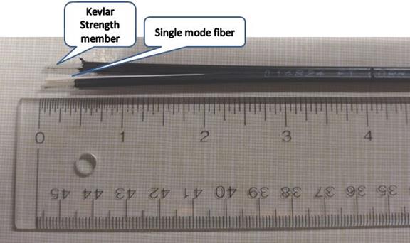
Figure 25 PON Drop Cable
The ONT (optical network terminal) converts the ISP optical signals to electrical and is often mounted on the outside of the dwelling and excess fiber coiled into a weather proof enclosure. Depending on the type of optical fiber used the ONT may or may not require to be grounded. In our case the fiber is nonmetallic so there is no need to ground the ONT. ONT power supply and possibility a backup battery are located inside the building near an always on AC receptacle. If POTS landline phones service is active inside wiring is disconnected from the copper NID (network interface device) and connected to the RJ11 jack on the ONT. A broadband router, often supplied by the ISP, is then connected to the Ethernet port of the ONT. This allows multiple devices to share the internet connection.
If TV service is purchased coaxial cable is run to each location for set top boxes. In most cases MoCA is used to connect the set top box to the service provider for billing and video on demand. However as previously mentioned not all fiber ISPs offer traditional TV service.

Figure 26 Consolidated Communications WiFi router and GPON ONT (circa 2022)
Consolidated used an Adtran 411 ONT for our fiber service. It provides a Gig Ethernet internet port and a RJ11 analog telephone port. It is tiny only about 3x5 inches. I was curious about it and found one on eBay. As someone who has been in the electronics field for decades it is amazing how much functionality can be packed into such a tiny package.
The ISP supplied router has dual-band WiFi and multi-port Gig Ethernet.
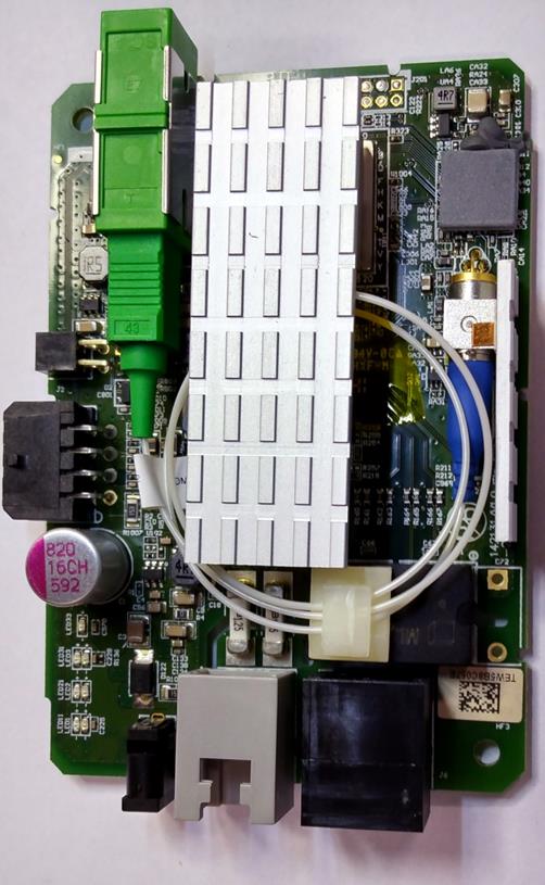
Figure 27 Adtran ONT Internal View
9 Fixed Wireless
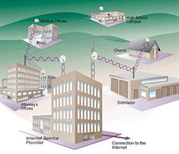 In areas not served by wired high-speed internet WISPs
(wireless ISP) are rushing to fill the void. WISPs use radios that operate in
licensed spectrum. Point-to-Point service may also be implemented using free
range optical links that do not have to be licensed but must meet safety
standards as pertains to eye damage due to the use of high power lasers.
In areas not served by wired high-speed internet WISPs
(wireless ISP) are rushing to fill the void. WISPs use radios that operate in
licensed spectrum. Point-to-Point service may also be implemented using free
range optical links that do not have to be licensed but must meet safety
standards as pertains to eye damage due to the use of high power lasers.
![]() The first question
that comes to mind is what is the difference between Cellular and WISP?
Cellular began life as a voice centric mobile service and added data as an
enhancement. Today the bulk of mobile cellular traffic is data due to the
popularity of smart phones. Cellular service is optimized for use while customer
is in motion where WISPs are optimized for fixed location use.
The first question
that comes to mind is what is the difference between Cellular and WISP?
Cellular began life as a voice centric mobile service and added data as an
enhancement. Today the bulk of mobile cellular traffic is data due to the
popularity of smart phones. Cellular service is optimized for use while customer
is in motion where WISPs are optimized for fixed location use.
WISPs use Point-to-Point and Point-to-Multipoint distribution. In some cases customer’s equipment functions as a router creating a mesh network expanding service footprint. In a PtP network a dedicated link is created between two locations. In a PtMP network a central hub services multiple customers.
Wireless ISPs use a central radio to cover a large territory eliminating need to run cable all the way to the customer’s location. Radio technology is ideal for rural areas where low population density makes installing copper or fiber uneconomic. As picture shows signal may take a direct path or if obstructions exist ISP may deploy repeaters. Repeater acts as a router forwarding packets and extending coverage area. Directional antennas can be used to create multiple sectors increasing total bandwidth.
9.1 WiMAX
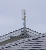 WiMAX (World
Interoperability for Microwave Access) was a trade association promoting this
evolving standard and hopes make it as successful in the metropolitan area
network (MAN) space as WiFi has become for local area networks (LAN).
Deployment is much more common outside the US then within the US. Distance is
about 10 miles in NLOS (non-line of sight) and 30 miles over LOS. Maximum data
rate is about 30 Mbps. As with other wireless technologies speed and distance
are inversely related, the greater the distance the lower the speed.
WiMAX (World
Interoperability for Microwave Access) was a trade association promoting this
evolving standard and hopes make it as successful in the metropolitan area
network (MAN) space as WiFi has become for local area networks (LAN).
Deployment is much more common outside the US then within the US. Distance is
about 10 miles in NLOS (non-line of sight) and 30 miles over LOS. Maximum data
rate is about 30 Mbps. As with other wireless technologies speed and distance
are inversely related, the greater the distance the lower the speed.
![]() WiMAX
is based on IEEE 802.16
specification for wireless metropolitan area networks (WMAN). 802.16 specify
operation between 2 - 66MHz. It is up to the WISP to choose the most
appropriate frequency band and obtain any required licenses.
WiMAX
is based on IEEE 802.16
specification for wireless metropolitan area networks (WMAN). 802.16 specify
operation between 2 - 66MHz. It is up to the WISP to choose the most
appropriate frequency band and obtain any required licenses.
9.1.1 Installation
The WISP normally supplies the radio equipment and installs it at the customer’s location. Customer is then able to use a residential router to share the connection.
9.2 WiFi Hot Spot
 The tremendous popularity
of IEEE 802.11 WiFi
created the phenomena of WiFi hot spots. All sorts of entities from libraries
to hotels to airports have installed public WiFi Access creating WiFi hot spots. Customer connecting
to the hotspot typically has to go through some type of portal experience. The
portal requires the user agree to certain terms and conditions. Once connected user
is able to access the internet. In some cases the service is free in others pay
to play.
The tremendous popularity
of IEEE 802.11 WiFi
created the phenomena of WiFi hot spots. All sorts of entities from libraries
to hotels to airports have installed public WiFi Access creating WiFi hot spots. Customer connecting
to the hotspot typically has to go through some type of portal experience. The
portal requires the user agree to certain terms and conditions. Once connected user
is able to access the internet. In some cases the service is free in others pay
to play.
![]() WiFi was designed as
a short-range wireless LAN. Attempts to provide citywide coverage using WiFi
Access Points has not been successful. The limited range of WiFi makes it
unsuitable as a MAN (metropolitan area network).
WiFi was designed as
a short-range wireless LAN. Attempts to provide citywide coverage using WiFi
Access Points has not been successful. The limited range of WiFi makes it
unsuitable as a MAN (metropolitan area network).
9.3 Free Space Optical Point-to-Point
Point-to-Point optical links are inexpensive compared to RF and very fast. The downside is birds, fog and snow obstruct transmission path.
|
Figure 31 Point to Point Free Space Optical Link |
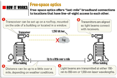
10 Satellite
Satellites act as a very tall antenna vastly expanding coverage area. Geosynchronous satellites occupy an extremely high orbit so they appear to be stationary. Low orbit satellites are being much lower require a large number to cover the earth.
10.1 Geosynchronous
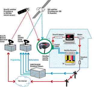 Science Fiction author Arthur C. Clark is generally
credited with proposing the notion of geosynchronous satellites in his 1945 paper Extra-Terrestrial Relays. On Earth
this distance is 22,236 miles above mean sea level, now called the Clark orbit.
Clark’s idea has been a boon to Radio and TV broadcasting.
Science Fiction author Arthur C. Clark is generally
credited with proposing the notion of geosynchronous satellites in his 1945 paper Extra-Terrestrial Relays. On Earth
this distance is 22,236 miles above mean sea level, now called the Clark orbit.
Clark’s idea has been a boon to Radio and TV broadcasting.
Satellite orbital time is a function of distance. The further a satellite is from earth the longer the orbit duration. Clark realized that at a certain distance orbital time would equal 24 hours. If the satellite is in equatorial orbit a 24-hour orbit means the satellite appears to stay positioned over the same spot permanently.
![]() The great height of geosynchronous satellite creates continent sized
signal footprint for each satellite. Since satellite appears fixed in space
expensive antenna tracking mechanisms are not required.
The great height of geosynchronous satellite creates continent sized
signal footprint for each satellite. Since satellite appears fixed in space
expensive antenna tracking mechanisms are not required.
When small aperture Direct Broadcast Satellite (DBS) TV became popular it was natural to adopt this technology to high-speed internet access. One-way implementation uses satellite link for high-speed download and dialup modem for upload. Two-way service uses satellite link in both directions.

Speed is a matter of transmit power and antenna size. As satellites have become more sophisticated transmit power has been increased resulting in greater down load speed.
Unfortunately the great height of geosynchronous orbit adds significant latency making this type of service more appropriate for large file transfer than interactive browsing. One-way latency Ground — Sat -- Ground is about ¼ second (250 ms). If the satellite is used in both directions latency is about 500 Ms. When dialup is used for upload total latency is reduced to about 350 ms. that is still too long for effective browsing or telephone service.
![]() Satellite capacity
is shared by many uses. Service providers implant Fair Access Policy to
allocate capacity equally to all customers.
Satellite capacity
is shared by many uses. Service providers implant Fair Access Policy to
allocate capacity equally to all customers.
10.2 Low Earth Orbit

To reduce latency satellites must be nearer to Earth. There have been several attempts to use LEO satellites to provide internet communication service. Covering the globe requires a constellation of hundreds or thousands of expensive satellites. The two early companies were Iridium and Teledesic.
The best know LEO satellite constellation is Starlink operated by SpaceX.
![]()
10.3 Installation
The ISP normally supplies the radio equipment and installs it at the customer’s location. Customer is then able to use a residential router to share the connection. Antenna needs an unobscured view of the satellite. Since geosynchronous satellites are in equatorial orbits antenna elevation gets depressed the further north you are. Starlink on the other had uses a fairly small flat antenna suitable for end user installation.
11 Cellular
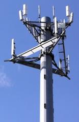 Unlike other wireless networks the
cellular network is designed to be used while the customer is in motion. Cellular
phone service is hugely popular. What started out as an expensive lunchbox sized 2-way radio a few decades ago is now smaller than a
pack of cigarettes and is considered an essential part of everyday life by much
of the world’s population. Some customers, especially younger ones, eschew
landline phone service in favor of a cell phone. 90% of American adults and 75%
of adults worldwide have internet access via mobile phones.
Unlike other wireless networks the
cellular network is designed to be used while the customer is in motion. Cellular
phone service is hugely popular. What started out as an expensive lunchbox sized 2-way radio a few decades ago is now smaller than a
pack of cigarettes and is considered an essential part of everyday life by much
of the world’s population. Some customers, especially younger ones, eschew
landline phone service in favor of a cell phone. 90% of American adults and 75%
of adults worldwide have internet access via mobile phones.
Some folks have gone so far as to rely solely on their smart phone for internet access or tether their phone to create a home network rather than pay for wired internet.
 The
attraction of wireless connectivity is not limited to voice. Almost from the
beginning the cellular network was pressed into data service, typically with
less than stellar results. Today Smart Phone usage is driving rapid conversion
of the network from one optimized for voice to one optimized for internet data.
The bulk of cellular traffic is now generated by internet access and streaming
content rather than voice. The advent of 4G LTE and 5G is causing mobile carriers
to rethink their business model.
The
attraction of wireless connectivity is not limited to voice. Almost from the
beginning the cellular network was pressed into data service, typically with
less than stellar results. Today Smart Phone usage is driving rapid conversion
of the network from one optimized for voice to one optimized for internet data.
The bulk of cellular traffic is now generated by internet access and streaming
content rather than voice. The advent of 4G LTE and 5G is causing mobile carriers
to rethink their business model.
The retail Cellular business model has evolved into two major components: Cell carriers and MVNOs (mobile virtual network operator). A MVNO purchases wholesale capacity from a Cell carrier and creates customer facing wireless plans. For example we use Boost Mobile.
An interesting chart about mobile internet.
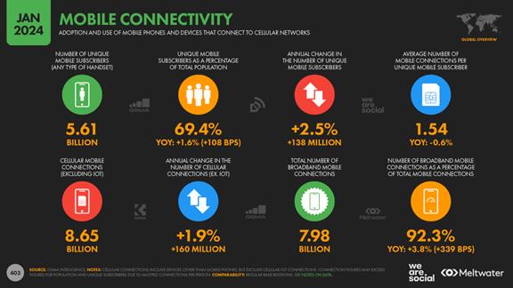
Figure 36 Global Mobile internet
11.1 Cellular Data Evolution
It is common to talk about the cellular network generationally 1st – 5th even though there is no hard and fast definition. 1st generation was the original analog circuit switched network in the 1980’s. 2nd generation was digital but still used circuit switching circa 1990’s. Early 2000’s saw the migration to 3rd generation digital spread spectrum optimized for internet access at 200 kbps data rate – the FCC definition of broadband at the time. Service providers then migrated to 4th generation LTE delivering 100 Mbps speed. Quite an accomplishment for a device you can hold in your hand while traveling at speed or in the skyscraper canyons of a modem city. Things move fast in the cellular world, no sooner was the 4th generated been deployed then the marketing machine cranked up talk about 5th generation. Hallmarks of 5G are: 1 Gbps speed, reduced latency, increased use of very high frequencies and micro cell sites.
United States is unique compared to the rest of the world where national cellular standards exist. The FCC chose not to mandate a particular standard. As a result we have a confusing patchwork of competing standards but this also allows companies to rapidly bring innovative services to market. Early cellular protocol was analog: AMPS (Advanced Mobile Phone System). The modern cellular network is digital. In the US some carriers use GSM (Global System for Mobile Communication) as does most of the rest of the world while others have adopted CDMA2000 (Code Division Multiple Access). With the increased emphasis on mobile internet that is changing and LTE has become a worldwide standard.
The tremendous popularity of mobile internet is driving adoption of more spectrally efficient transmission standards to increase speed and the need for more RF bandwidth to increase channel capacity. Cellular carriers are clamoring for more bandwidth. In the aftermath of the US transition from analog to digital TV in 2009 channels 51-69 were auctioned off. Much of that spectrum is used to expand the cellular data network. More recently the FCC auctioned additional TV channels (38-50) and has made additional microwave bands available for cellular.
Data rate is a complex interaction affected by: channel size, power, interference and modulation. Due to the nature of radio communication throughput is often significantly slower than peak data rate. None the less modem cellular network provides meaningful high speed access pretty reliably.
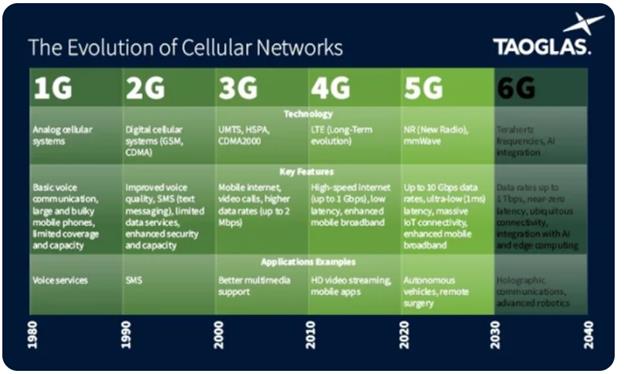
Figure 37Evolving Cellular Data Standards
11.1.1 1st Generation Cellular Digital Packet Radio
CDPD is the granddaddy of wireless data service. It used the AMPS (analog advance mobile phone system) to deliver an anemic 9.6 or 14.4 kbps. Due to the heavy compression used on the cellular network dialup speed is significantly lower than landline PSTN US carriers stopped supporting CDPD in 2005.
11.1.2 2nd Generation General Packet Radio Service
GPRS data rate is in the 100kbps range.
11.1.3 3rd Generation CDMA2000 - Evolution Data Optimized
Modern Cellular network is digital capable of much faster data transport then early analog system. EvDO rev A delivers download speed in the 3.1 Mbps range. Rev B increases speed to 4.9 Mbps per channel
11.1.4 3rd Generation GSM – Enhanced Data Rates for GSM
EDGE is an enhancement to GPRS delivering 300 kbps.
11.1.5 3rd Generation UMTS - High Speed Downlink Packet Access
HSDPA is an all-digital packet technology. Data rate is around 14 Mbps.
11.1.6 3rd Generation UMTS – Evolved High Speed Packet Access (HSPA+)
HSPA+ is an evolution of HSPA that dramatically increases speed while maintaining the same radio interface. HSPA+ delivers up to 168Mbps toward the user and 22 Mbps up. In the US AT&T and T-Mobile have adopted HSPA+
11.1.7 Pre4th Generation 3GPP Long Term Evolution
LTE is part of the Third Generation partnership project for GSM networks (3GPP). Focus is migrating cellular data to packet based, rather than circuit switched network and delivering substantially higher speed then today’s cellular network. LTE delivers Multi-megabit speed with very low latency. Data rate is in the 100-300Mbps down 50-75Mbps up.
11.1.8 4th Generation 3GPP LTE Advanced
Long Term Evolution Advanced is the next generation version of LTE that meets all the requirements set forth in 3GPP for 4th generation radio. 1Gps aggregate data rate down, 500 Mbps up with improved spectral efficiency.
11.1.9 5th Generation
Mobile generations come every decade or so. 5th generation is optimized for internet data. Super high millimeter wave promises blazing fast speed but due to propagation loss only over extremely short distances.
11.2 WiFi Calling
It is pretty common now to have cell phones and carriers support WiFi calling. When the phone is connected to a WiFi network calls and texts are carried over the WiFi network rather than the cellular network. Emergency calls are still transported by the cellular network to preserve location data. This works well for both customers and cellular carriers as it moves traffic off the cellular network.
11.3 Tethering
Tethering is an interesting way to use your cell phone to connect one or more additional devices. Depending on the phone the LAN connection may be USB, Bluetooth or WiFi. If the phone includes router capability you can connect multiple devices, if not will need an external router.
11.4 5G Home Internet aka Fixed Wireless
Some carriers in the 5G space are offering home internet service. I was initially skeptical this would be capable of delivering adequate performance in dense urban areas but so far at least anecdotally customers seem happy with the service and it should be a boon for folks who move around a lot, time will tell.
11.5 Cellular Issues
11.5.1 Roaming Charges
Connectivity costs vary dramatically. Cost is low when using your providers cellular network and much higher when out of range requiring voice or data to be transported by another carrier, called roaming. Cell phones often have a way to limit how apps connect when roaming to minimize cost.
11.5.2 Locked Phones
Phones purchased through the carriers are often bound to a particular carrier’s network and cannot be easily moved to a competitor. In the US the FCC is looking into limiting carrier’s ability to permanently lock phones
11.5.3 Caps
Most Cellular data plans have relatively low monthly data usage limit with significant overage charges. High speed streaming available to cellular subscribers makes it easy to blow through monthly cap streaming video. Carriers typically provide a warning when customer is close to hitting their cap.
11.6 Installation
Being mobile there is no installation. Increasingly providers are moving away from subsidizing handsets as part of a multiyear contract. In general FCC number portability can be used to transfer your existing wired or wireless phone number to a new carrier. This usually involves getting a pin from your current carrier allowing the new carriers to transfer the number in order to prevent slamming, the unauthorized transferring of a number to a different carrier.
Where cellular service is sold as residential broadband the radio and antenna is mounted exterior to the house as with traditional WISP and a router is used to share the connection.
Closing Thoughts
The internet represents a fundamentally new method of human communication as important as the written word and the printing press.
Never before has it been so easy and inexpensive to communicate with anyone on the planet.
Never before have ordinary citizens owned the printing presses.
Never before have citizens been able to band together so effectively to express their support or displeasure at government or business.
Never before has it been as easy to create original audio, visual and written works.
Never before have creators and patrons been so closely interconnected.
However: as with all technology this powerful ability to communicate globally has a down side. Misinformation and hate can now be spread worldwide to nearly everyone at the speed of light.
The coming decades will profoundly change human civilization.