|
|
|
External Battery DC Output UPS |
|
|
|
|
|
Tom Schmidt |
|
|
Revised 1/8/2025
Originated 7/26/2018
|
I wanted to maintain internet access and landline phone during power outages when our backup generator was not running. To do this we need to keep several network devices powered. Luckily they all use DC wall warts so the obvious solution is a DC, rather than AC, output UPS. The UPS has a high current charger/maintainer to charge the battery quickly and keep it fully charged over time. A separate 12 volt supply powers the LAN when mains power is available. A rather unique aspect of this design is the use of an automotive jump pack rather than build the battery into the UPS chassis. With this setup the LAN remains operational for hours without AC power. If mains power is available the jump pack can be removed and used as needed without affecting network operation. |
Table of Contents
Overview
In 2016 I installed a portable generator to provide power during utility outages. Our intent is to run the generator a few hours in the morning and evening. This means we lose internet access when the generator is not running. In addition now that we have fiber it means we lose landline phone as it is implemented as VoIP by our ISP. Our essential network devices are powered by DC wall warts. It is inefficient to utilize a traditional UPS to convert battery power to AC and then back to DC to operate the LAN. I wanted to build a UPS that output DC, eliminating the need for wall warts to keep our LAN and phone operational during a power outage.
The UPS is built into an old TiVo Series II chassis. I’ve used them for several other projects as it is a nice sturdy metal chassis. Removing the front plastic trim panel reveals a solid metal panel except for a few small holes.
I could have used any appropriately sized SLA (sealed lead acid) battery to provide backup power but opted to use an automotive power pack. This is basically a SLA battery in a portable carrying case. With this arrangement we have the best of both worlds. The jump pack keeps the LAN running when mains power fails and the UPS keeps the jump pack charged ready to use. A Deltran 5A battery tender is used to charge the battery. The high current capability is able to recharge the battery in three to four hours. This is important as we only intend to use the generator a few hours a day. Once the battery is charged the battery tender enters maintainer mode. This keeps the battery topped up while not over charging it. The built-in jump pack charger is not suitable for UPS usage as it takes a long time to charge the battery and it does not have a maintainer mode.
The UPS is connected to the jump pack through one of its accessary power (cigarette lighter) sockets. The power pack can be unplugged if needed, without affecting LAN operation as along as AC power is available.
A separate 12 volt 5A DC switch mode power supply powers network equipment when mains power is available. This way there is no load on the battery minimizing recharge time. When AC power fails the system switches to battery and a low voltage monitor function protects the battery from being too deeply discharged.
Network power requirements
We have gone through various generations of network equipment over the life of the UPS. Originally we had DSL and now PON (passive optical network). Currently there are three devices that are powered during an outage. The ONT (optical network terminal), WiFi router and Ethernet switch. The Ethernet switch is not absolutely necessary but keeping it powered enables access to our home server and allows devices to connect via Ethernet instead of being limited to WiFi. The server has its own battery. A 5V buck converter was used during our DSL days however it is no longer required. I left the module in the chassis but disconnected the input. The ONT includes landline phone emulation so no additional equipment is needed to support POTS (plain old telephone service).
Typical 12 volt current draw of each device is shown below. The current configuration has about the same power requirements as the old DSL system.
|
Device |
Wall Wart |
Typical current |
|
Fiber ONT |
12V @ 1.0A |
.170A (.210 POTS off hook) |
|
WiFi router |
12V @ 1.5A |
.240 (2 active enet ports) |
|
Ethernet switch |
12V @ 1.0A |
.282A (10 active ports |
|
|
|
.692A total |
Design considerations
When using the UPS all network devices share a common ground, this is different than when each device is powered by a dedicated wall wart. I verified each chassis is tied to the negative DC power rail. If some devices tie the positive rail and others negative touching them together will short out the UPS. It is common engineering practice to tie negative to the chassis and that is the case for all our gear. Ethernet data lines are transformer coupled so it is not affected by how the device is powered. The PoE (power over Ethernet) specification uses an isolated power converter in the powered device; however there are many different implementations so it is good to double check. In our case none of our gear uses PoE.
The power pack battery as purchased is rated at 17AH at a 20 hour rate so should have enough capacity to operate the network for at least 10 hours without discharging it too deeply. The Battery tender is rated at 5 Amps; this is the maximum recommended charging current for the SLA battery. As such it should be able to recharge a depleted battery in 3-4 hours.
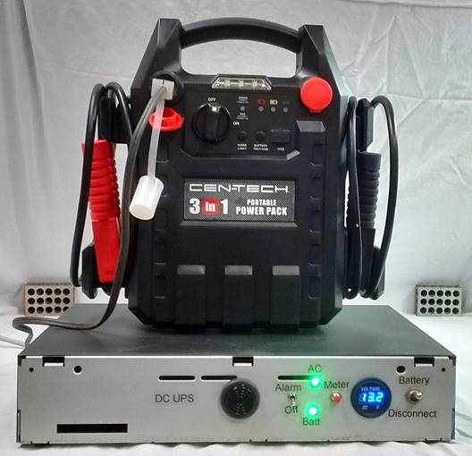
Figure 1 DC UPS system
Automotive jump pack
I purchased a Harbor Freight power pack on sale in 2018, which prompted me to build this UPS. It consists of a 17 AH SLA battery, jumper clamps controlled by a switch, work light, battery charge indicator, USB power port, two accessary power sockets and a built in AC charger. The built in charger is not used by the UPS as it is too slow and will over charge and damage the battery if left powered continuously. The battery is charged by the battery tender in the UPS. This insures it is fully charged at all times without risk of damaging the battery. I did not remove the internal charger as this allows the power pack to be recharged when remote from the UPS.
The two accessary sockets are always live, protected by an internal circuit breaker. This provides convenient access to the battery. An accessary plug (cigarette lighter plug) connects the UPS to the power pack.
If the power pack is needed elsewhere just remove the UPS accessory plug. The battery maintainer is smart and automatically removes power from the plug when it detects the battery is not connected. Removing the power pack has no effect on the LAN as long as AC power is available.
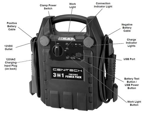
Figure 2 Automotive power pack
UPS
I mounted the other components in an old TiVo Series II chassis. It houses everything except the battery power pack. The main UPS components are:
· 12 volt 5 Amp power supply
· Deltran 5 Amp power tender battery maintainer
· ATC style 6 position fuse block
· DC to DC buck converter (provides 5 V for DSL router, no longer needed)
· Digital volt meter
· Logic board
Currently there are three devices that need power to maintain LAN and phone: ONT (optical network terminal), WiFi router and Ethernet switch. I designed the UPS to be able to supply a maximum of 5 amps at 12 volts. A DC to DC switch mode buck converter module provides 5 volts (no longer used).
When AC power is available a 12 volt 5 amp switch mode power supply provides LAN power. This allows the battery to be recharged as quickly as possible as there is no load on it and the power pack can be removed and used elsewhere if needed without affecting the LAN. This also isolates the network gear from the slightly higher battery charging voltage.
When AC power is available the power pack is disconnected from the load and charged by the battery tender. This is a 5 Amp unit so it is able to recharge the battery in 4-5 hours as well as maintaining the battery at full charge without risk of over or under charging. For a 100+ year old technology the optimum charging requirements of lead acid batteries are pretty complex. Power Sonic has a nice whitepaper about charging lead acid batteries for those interested in the gory details.
A simply voltage monitor activates a power transfer relay if the AC derived 12 volt supply drops by a volt. The LAN is then powered by the power pack battery. Lead acid batteries are sensitive to over discharge and will be permanently damaged if deeply discharged. Another voltage monitor disconnects the load if battery voltage drops too low. When the relay is released the load is removed from the battery.
In addition to the automatic low voltage disconnect there is a battery disconnect switch. This can be used at night when everyone is in bed and there is no need to keep the LAN and phone operational. Turning the switch off prevents the power transfer relay from energizing. When the battery disconnect switch is turned back on the transfer relay is momentarily activated. If there is enough power remaining in the battery and AC power has not been restored the LAN is powered from the battery. The switch only disconnects the battery from the load; the battery is always connected to the charger/maintainer. Regardless of battery switch position if AC power is available the LAN is powered from the 12V 5A supply.
Low battery threshold
The open circuit voltage of lead acid batteries varies due to state of charge, as a result of chemical changes within the battery. A freshly charged 12 V battery will have an open circuit voltage of about 13.1 volts. This varies a little depending on the voltage used to charge the battery and temperature. 11.6 volts is considered fully discharged for a 12 volt battery.
The fully discharged voltage under load is dependent on the discharge current. The higher the current the lower the terminal voltage and the battery will not be capable of delivering the full rated amp hour capacity. In our case we are discharging the battery at approximately the .05C rate. Theoretically the battery can power the LAN for up to 25 hours. However fully discharging lead acid batteries significantly shortens their life.
A complicating factor is that we are not measuring voltage directly at the battery but through cables, connectors and a circuit breaker. As a result there is about a 200 millivolt drop between the battery and controller at a 1 ampere load. This results in the voltage at the battery being .2 volts higher than at the monitoring circuit when the battery is under load.
Using the Power Sonic document as a guide battery voltage at 100% of capacity is 12.6V, at 50% remaining capacity voltage is 12.0V, dropping down to 11.5V at 25% when discharged at a .05C rate. I set the disconnect level at 11.6V, equating to 11.8V at the battery.
I set the discharge limit fairly aggressively to maximize battery run time at the expense of battery life. We only expect a week long power outage every couple of years so a slight reduction in battery life due to deep discharge is acceptable. The deleterious effects of deep discharge are somewhat minimized as the battery is quickly recharged once AC power is available and not left in the discharge state to sulfate.
Switches and indicators
The UPS front panel has a number of switches and indicators. The jump power pack is treated as a black box, all controls and indicators are on the UPS. The battery maintainer has two status LEDs that are visible through the USB front panel. They are not used for normal operation but proved handy during testing.

Figure 3 UPS Front panel
Battery disconnect switch – this is used when the LAN can be shutdown to minimize unnecessary battery drain. This disconnects battery from the load, the battery tender remains connected so the battery is recharged whenever AC is available. When the battery is switched back on the transfer relay is momentarily energized. If the battery is not fully discharged and AC power has not been restored the LAN is powered up. If AC power is restored the LAN is powered from the AC 12V supply regardless of battery switch position.
DC voltmeter – small motorcycle digital voltmeter displays battery voltage. When AC power is available a MOSFET provides a low resistance ground enabling the meter to display battery voltage. When AC power is lost it disconnects the ground turning the meter off to reduce battery drain.
Voltmeter pushbutton – when the meter is off pressing this switch grounds the low side of the meter activating the display.
AC status indicator – green LED powered by the 12 volt power supply. It is illuminated when AC power is present.
Battery status indicator – green indicates nominal battery voltage, red if outside this range. The range is set fairly narrow to monitor battery status. Red if the voltage is too high or the tender fails and battery voltage falls due to self-discharge.
Battery alarm switch and sounder – pulsating audible alert if battery voltage is too high or low when AC power is available. Same thresholds as the red battery LED. The alarm should be turned off during AC fail events when battery is being charged as the voltage then exceeds normal maintainer range.
External connections
The USP is located in the same equipment closet as the Ethernet switch. The ONT and WiFi router are located some distance away. I strung 2-conductor 18 AWG cable to a terminal block located near the ONT and router. All devices use barrel jacks for power so I connected barrel jacks with a short pigtail to the terminal block.
I had a nice heavy gauge cigarette lighter cord set laying around so used it to connect the UPS to the power pack. Plug has a protective plastic cap that can be snapped on when not in use. For safety the battery tender will not energize the plug if it detects the battery is disconnected, but it is nice to have mechanical protection when the jumper pack is disconnected.
The UPS uses an IEC C14 power inlet and C13 detachable 3-wire AC line cord. The cord is plugged into a high end surge protector. The IEC receptacle is fused and feeds power to the battery tender and 12 volt SMPS.
The 12 volt supply output is protected by 7.5 amp ATC fuse then fed to the logic board transfer relay. The output of the relay feeds a 2 amp ATC fuse for each load; only three are currently used. Presently all three network devices require 12V DC.
The heart of the logic board is an LM336 2.5 volt reference and LM339 quad comparator. Two comparator sections act as a wired OR to control the transfer relay. One section monitors the 12 volt supply the other battery voltage. If the AC supply drops below 11.6 volts and battery voltage is above cutout value the transfer relay is energized powering the LAN from the battery. When AC power is present or battery voltage is too low the relay is deenergized disconnecting the battery and powering the LAN from the AC supply. A couple of 1000uf 25V caps provide bulk storage so voltage does not sag too much while the relay is switching between AC and battery.
The AC 12 volt supply output increases slightly when the load is removed so the comparator uses a couple hundred millivolts of hysteresis to prevent false triggering during power fail events. Similarly when the battery load is disconnected battery voltage increases substantially due to its internal resistance. I used capacitive feedback to temporally drive down the battery sense voltage threshold. When battery voltage falls to the disconnect threshold the transfer relay is de-energize causing Vcc to decay, the capacitive feedback prevents the relay from being prematurely turned on while Vcc is falling.
Two more comparator sections form a window comparator driving the red/green battery status indicator and the audible alarm. The thresholds are set around maintainer mode voltage. This way it will alert if the maintainer fails and either over charges or allows battery voltage to fall due to self-discharge.
Another comparator section controls the fan. The TiVo chassis has a nice little 12V DC fan. I clipped a thermistor to the 12 volt supply heatsink feeding a simple bridge circuit. When temperature exceeds 93 F the fan turns on.
An ULN2803A 8 port Darlington array drives the relay, fan and indicators. The outputs are connected to different voltage rails so the built in snubber diodes cannot be used.
AC power consumption
The 12 volt 5 amp supply is rated at 84% efficiency so it dissipates 11.5Watts at full load. Deltran does not specify power tender efficiency. I assumed 75% (14V 5A) so it dissipates 23 watts. The UPS logic and display consume less than a watt. Network devices are external to the UPS so they do not contribute to UPS chassis heating. Maximum internal chassis power dissipation is 35 watts due to inefficiencies of both power supplies.
Worst case AC power consumption is 165 W, this occurs under full LAN loading (5 Amp) and high current battery recharge (5 Amp). Nominal AC power consumption with LAN operating and battery being charged is 99 watts. Once the battery is charged AC power drops to about 16 watts.
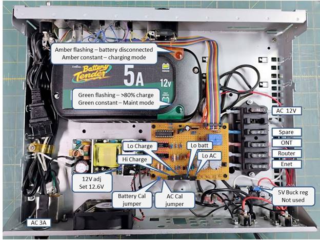
Figure 4 UPS adjustments and fuses
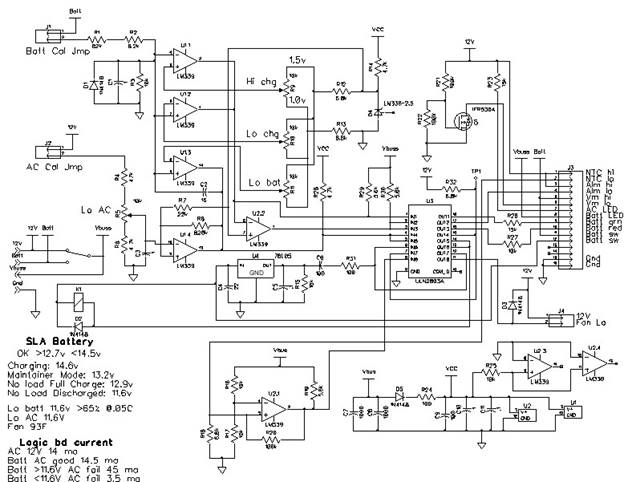
Figure 5 Logic board
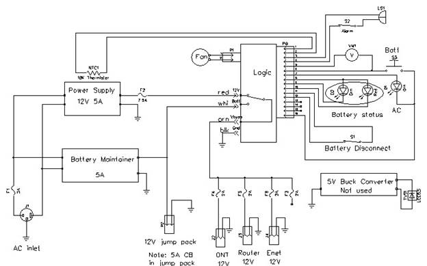
Figure 6 Power wiring
Cost rollup
I had most of the small components in my parts stock so do not have an accurate accounting of total cost. 2018 estimated cost shown below.
|
Item |
Cost |
|
5 Amp Battery Tender |
$58.00 |
|
3 in 1 Automotive power pack |
$40.00 |
|
100 Amp battery load tester |
$18.00 |
|
12V 5A switch mode power supply |
$14.00 |
|
TiVo Series II chassis |
$10.00 |
|
Motorcycle DC voltmeter |
$7.00 |
|
2A ATC fuses |
$5.50 |
|
6 position ATC fuse holder |
$4.00 |
|
Audible Alarm |
$4.00 |
|
12V SPDT 10A relay |
$1.00 |
|
DC/DC buck converter |
$1.00 |
|
Misc. components (Est) |
$40.00 |
|
Total |
$202.50 |
Operation
During normal operation the battery and alarm switches are in the on position. As long as AC power is available network gear is powered by the 12 volt 5 amp supply and the battery tender keeps the battery toped up.
If the battery tender fails it will either over charge the battery or more likely the battery will self-discharge enough to turn the battery LED red and set off the audible alarm indicating the need for corrective action. It is a good practice to periodically observe battery voltmeter. It should be between 13.0-13.2 volts. This is the safe maintainer mode voltage, high enough to keep the battery fully charged but low enough to prevent overcharge. The maintainer pulses the maintainer mode voltage, but the meter displays average voltage.
During an outage the 12 volt power supply output will quickly decay. When it falls by a volt the UPS switches to battery. The LAN remains powered from the battery until its voltage drops too much or AC power is restored.
When AC power is restored the transfer relay is deenergized and network load switched back to the 12V power supply and the battery tender cycles though battery the charging regime. This voltage is high enough to activate the audible alarm. During an outage turn the alarm off prevent nuisance alert. The audible alarm is only active when AC power is available.
During an outage when the LAN isn’t needed flip the battery disconnect switch off minimizing unnecessary battery drain. Don’t forget to turn it back on as needed. Even with the battery switch off when AC power is restored the LAN will be powered up and battery charged. Once mains power has been restored and the battery fully charged flip the audible alarm switch back on.
Every year of so perform a battery load test and replace the battery as needed.
Battery run and charge time
To verify run and charge time I used a 12V bulb to simulate the network gear. It draws 920ma - 900ma depending on battery voltage. This is not a perfect analog to networking gear as the bulb draws less current as voltage goes down whereas a switch mode power supply draws more. To bracket the test I ran it again using a 20 ohm resistor resulting in a 620ma load.
At 910ma system ran for 12 hours consuming 11AH or 65% of total battery capacity. At the end the open circuit battery voltage was 11.9 indicating about 30% of remaining capacity left. At 620ma system ran for 17.25 hours consuming 10.5AH or 61% of total battery capacity. The open circuit battery voltage was 12.0V indicating about 35% of remaining capacity left. Run time is compatible with how we intend to use the backup generator, so no sense opting for deeper level of discharge. The run time test was conducted with the original 17AH battery, I have not retested run time with the replacement 22 AH battery.
Recharge took 45 minutes to hit 80% state of charge and a little less than 3 hours for full recharge. I was a little worried the additional cable resistance would increase charge time but the charger has enough voltage compliance to compensate. Charge current maxed out at 4.88A right where is should be for a 5A charger.
Monitoring battery capacity
The smart charger/tender does a good job maximizing battery life but lead acid batteries are the Achilles heel of any electronic project as they have relatively short life expectancy, under ideal conditions typically five years or so. I wanted to be able to periodically test the battery and replace it before it has lost so much capacity to be useless during a power outage.
There are lots of fancy battery load testers but I went with a simply old school unit with an analog volt meter and low value high power resistor that loads the battery at approximately 100 Amps. The 100 Amp specification is rather lose because the resistive load only draws 100 Amps at 12 volts. These testers have been around for years. I purchased mine from Harbor Freight along with the automotive jump power pack.
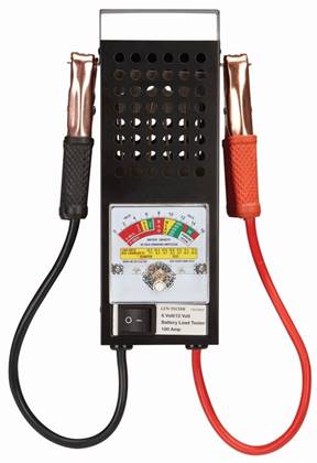
Figure 7 Battery load tester
Using the tester is easy. Connect the test clips to the battery terminals. The meter will indicate no load battery voltage. This should be between 12.8-13.2 volts for a fully charged battery. The open circuit voltage is affected by surface charge and varies some depending on how recently the battery was charged and to what voltage. Pressing the test switch connects a low value high wattage resistor to the battery (.120 ohms). The meter displays the resulting battery voltage. The higher the cold cranking amp (CCA) rating the less voltage should drop under load.
I connected the tester to the power pack battery clamps and activated power to the clamps. The load tester displayed open circuit voltage of 13 volts. Voltage decreased to 10 volts when the load button was pressed. I used a clamp-on DC amp meter and measured a load current of 82 amps. Testing the power pack battery this way somewhat understates its capacity since the load is being drawn though the power pack switch and cables. But for our purposes that is fine. I’m not that concerned with the absolute value. What I want to do is establish a base line and then every year or so recheck battery capacity. If the voltage under load begins to fall much below 10 volts I know the battery is losing capacity and should be replaced.
Given the low price of the Harbor Freight power pack it will be interesting to see how long the battery lasts. I assume it is by far the most expensive component of the unit. Curiously the jump pack battery is rated at 17AH. I noticed other same sized SLA batteries are rated at 18AH.
UPS modifications
I’ve made several changes to the UPS over the years as our internet access has changed. Our local Telco is aggressively rolling out PON (passive optical network). Prior to this our internet access was via DSL and we maintained a telephone landline, both provided by a CLEC (competitive local exchange carrier). DSL required power for the DSL router, Ethernet switch and WiFi Access Point.
October 2021 – Yea Fiber internet for us
Moving to fiber changed the devices the UPS needs to power. They now consist of: ONT (optical network terminal) that converts fiber to Gig Ethernet and provides POTS (plain old telephone service) landline, a WiFi internet router and the Gig Ethernet switch. The Ethernet switch and UPS are in the same wiring closet. I ran a two conductor cable from the UPS to the ONT and WiFi router. Previously the WiFi access point was powered by stealing two pairs in an Ethernet cable.
In the original design the battery disconnect switch was on the load side of the battery. I modified the circuit so instead it now prevents the battery change over relay from actuating. The DSL router required 5 volts, hence the need for the buck converter. With fiber all devices now use 12 volts so I disconnected the buck converter but left it in the chassis in case it is needed in the future.
October 2023 Customer WiFi router
I replaced the ISP WiFi router with a Netgear RAX 10. This yielded slightly better WiFi coverage and significantly reduced power consumption. All I needed to do from a UPS perspective was change the DC barrel jack power plug.
May 2024 Battery replacement
The jump pack came with a 17AH SLA battery. I found a Mighty Max ML22-12 22AH AGM SLA battery the same size. I decided to replace the original battery at the 5-year mark. Hopefully the 22AH battery will increase in run time by 30% for a few bucks more than a generic replacement 18AH SLA. I have not rerun the battery load test with the new battery as that requires taking the LAN out of service for the duration of the test.
January 2025 Battery changeover inhibit
In order to restart the UPS during a power outage the transfer relay is momentarily energized when battery power is first applied. What I overlooked with the original design is it does this even when AC power is available. That does not break anything but is sloppy so I added an inhibit circuit to prevent it from occurring when AC power is available.
Conclusion
It is comforting to know in the event of a power outage we will be able to maintain internet access and landline telephone as long as we have gas to occasionally run our generator and recharge the UPS. My wife and I each have a laptop in addition to our desktop PCs. So we will be able to use them during an outage to binge on the internet.
During a power outage our PON VoIP landline will remain operational when the generator is running and when not for as long as the USP battery lasts. In addition we have our cell phones for emergency communications and browsing.
So far we have only used the USP once several years ago when wind took out a few trees along our driveway that broke the top of one of the utility poles killing power. Interestingly the fiber optic cable survived so we did not lose internet or landline.
All in all an interesting and rewarding project.
Intentionally blank